Incorrect setting of multi-function contact
inputs.
• Check if the unused terminals set for H1-
= 20 to 2F (External Fault).
• Change the terminal settings.
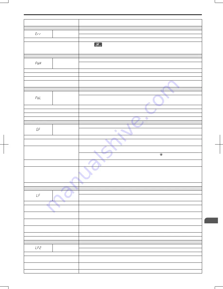
LED Operator Display
Fault Name
Err
EEPROM Write Error
Data does not match the EEPROM being written to.
Cause
Possible Solution
-
•
Press the
button.
• Correct the parameter settings.
• Cycle power to the drive.
Refer to Diagnosing and Resetting Faults on page 252
.
LED Operator Display
Fault Name
FbH
Excessive PID Feedback
PID feedback input is greater than the level set b5-36 for longer than the time set to b5-37. To enable
fault detection, set b5-12 = “2” or “5”.
Cause
Possible Solution
Parameters are not set appropriately.
Check the settings of parameters b5-36 and b5-37.
Wiring for PID feedback is incorrect.
Correct the wiring.
There is a problem with the feedback sensor. • Check the sensor on the control side.
• Replace the sensor if damaged.
LED Operator Display
Fault Name
FbL
PID Feedback Loss
This fault occurs when PID Feedback Loss Detection is programmed to fault (b5-12 = 2) and the PID
Feedback < PID Feedback Loss Detection Level (b5-13) for the PID Feedback Loss Detection Time
(b5-14).
Cause
Possible Solution
Parameters are not set appropriately.
Check the settings of parameters b5-13 and b5-14.
Wiring for PID feedback is incorrect.
Correct the wiring.
There is a problem with the feedback sensor. Check the sensor on the controller side. If damaged, replace the sensor.
LED Operator Display
Fault Name
GF
Ground Fault
• Current shorted to ground exceeded 50% of rated current on output side of the drive.
• Setting L8-09 to 1 enables ground fault detection in models 5.5 kW or larger.
Cause
Possible Solution
Motor insulation is damaged.
• Check the insulation resistance of the motor.
• Replace the motor.
A damaged motor cable is creating a short
circuit.
• Check the motor cable.
• Remove the short circuit and turn the power back on.
• Check the resistance between the cable and the ground terminal .
• Replace the cable.
The leakage current at the drive output is too
high.
• Reduce the carrier frequency.
• Reduce the amount of stray capacitance.
The drive started to run during Current Offset
Fault or while coasting to a stop.
• The value set exceeds the allowable setting range while the drive automatically adjusts the current
offset (this happens only attempting to restart a PM motor that is coasting to stop).
• Enable Speed Search at start (b3-01 = 1).
• Perform Speed Search 1 or 2 (H1-
= 61 or 62) via one of the external terminals.
Note:
Speed
Search 1 and 2 are the same when using PM OLV.
Hardware problem.
• Replace the drive.
LED Operator Display
Fault Name
LF
Output Phase Loss
• Phase loss on the output side of the drive.
• Phase Loss Detection is enabled when L8-07 is set to “1” or “2”.
Cause
Possible Solution
The output cable is disconnected.
• Check for wiring errors and ensure the output cable is connected properly.
• Correct the wiring.
The motor winding is damaged.
• Check the resistance between motor lines.
• Replace the motor if the winding is damaged.
The output terminal is loose.
• Apply the tightening torque specified in this manual to fasten the terminals.
Refer to Wire Size on
page 52
.
The motor being used is less than 5% of the
drive rated current.
Check the drive and motor capacities.
An output transistor is damaged.
Replace the drive.
A single-phase motor is being used.
The drive being used cannot operate a single phase motor.
LED Operator Display
Fault Name
LF2
Output current imbalance
One or more of the phases in the output current is lost.
Cause
Possible Solution
Phase loss has occurred on the output side of
the drive.
• Check for faulty wiring or poor connections on the output side of the drive.
• Correct the wiring.
Terminal wires on the output side of the drive
are loose.
Apply the tightening torque specified in this manual to fasten the terminals.
Refer to Wire Size on
page 52
.
No signal displays from the gate driver board. Replace the drive. Contact OYMC or an OYMC representative for assistance.
6.4 Fault Detection
SIEP C710606 20 OYMC AC Drive - V1000 User Manual
233
6
Troubleshooting
7/16/2008-13:23
Содержание V1000
Страница 11: ...Table of Contents This Page Intentionally Blank 10 SIEP C710606 20 OYMC AC Drive V1000 User Manual ...
Страница 27: ...1 4 Component Names This Page Intentionally Blank 26 SIEP C710606 20 OYMC AC Drive V1000 User Manual ...
Страница 37: ...2 2 Mechanical Installation This Page Intentionally Blank 36 SIEP C710606 20 OYMC AC Drive V1000 User Manual ...
Страница 63: ...3 12 Wiring Checklist This Page Intentionally Blank 62 SIEP C710606 20 OYMC AC Drive V1000 User Manual ...
Страница 221: ...5 11 U Monitor Parameters This Page Intentionally Blank 220 SIEP C710606 20 OYMC AC Drive V1000 User Manual ...
Страница 273: ...7 5 Drive Replacement This Page Intentionally Blank 272 SIEP C710606 20 OYMC AC Drive V1000 User Manual ...
Страница 287: ...8 6 Connecting an Option Card This Page Intentionally Blank 286 SIEP C710606 20 OYMC AC Drive V1000 User Manual ...
Страница 297: ...A 6 Drive Derating Data This Page Intentionally Blank 296 SIEP C710606 20 OYMC AC Drive V1000 User Manual ...
Страница 379: ...C 13 Self Diagnostics This Page Intentionally Blank 378 SIEP C710606 20 OYMC AC Drive V1000 User Manual ...
Страница 409: ...Index This Page Intentionally Blank 408 SIEP C710606 20 OYMC AC Drive V1000 User Manual ...
Страница 410: ...This Page Intentionally Blank SIEP C710606 20 OYMC AC Drive V1000 User Manual 409 ...


