


D.4 Safe Disable Input Precautions
u
Safe Disable Function Description
The Safe Disable function can be utilized to perform a safe stop according to the EN60204-1, stop category 0 (Uncontrolled
stop by power removal). It is designed to meet the requirements of the EN954-1, Safety Category 3 and EN61508, SIL2.
Removing the voltage from terminals H1 and H2 disables the drive output, i.e. the power supply to the motor is cut by
stopping the switching of the output transistors in a safe way. “Hbb” is shown on the display. Always use both inputs to
disable the drive. If for any reason only one channel is opened, the drive output is stopped too but the display shows
“HbbF”. In this case the Safe Disable input wiring must be checked. Safe Disable is applicable for induction and permanent
magnet motors.
u
Installation
If the Safe Disable function is utilized, the wire link between the terminals HC, H1 and H2 that is installed at shipment
must be removed entirely.
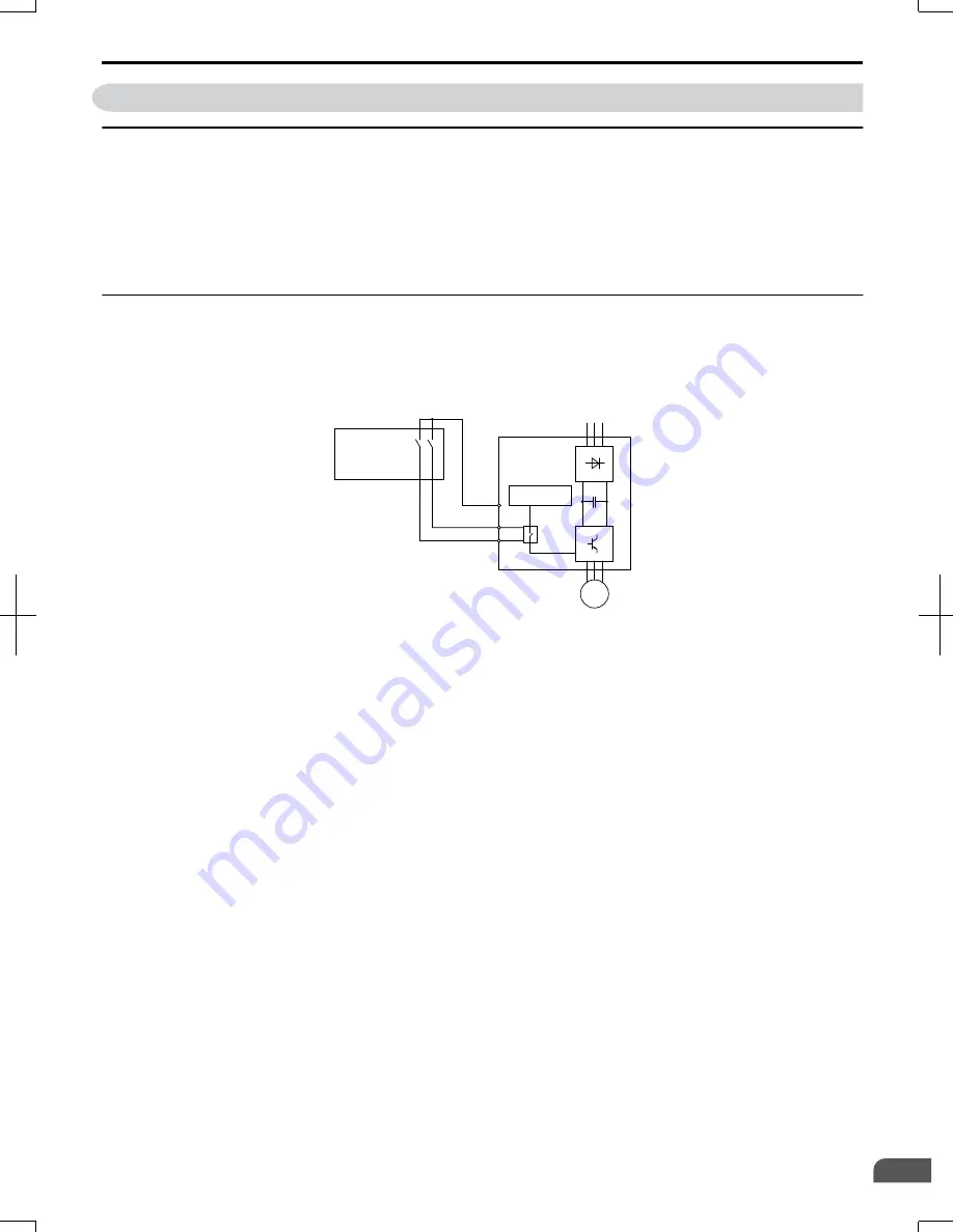
Connect the drive to an EN954-1, Safety Category 3 interrupting device so that in case of a Safe Disable request the
connection between terminal HC and both terminals H1 and H2 is opened.
Power Supply
Controller
HC
H2
EN954-1 Safety
Cat. 3 Device
M
Drive
H1
Figure D.9 Safe Disable Wiring Example
n
Installation Precautions
• To ensure the Safe Disable function appropriately fulfills the safety requirements of the application, a thorough risk
assessment for the safety system must be carried out.
• If only one signal line from the safety device to the drive is used (H1 and H2 are linked at the drive), the drive must be
installed in an enclosure with protection degree of at least IP54 in order to maintain EN954-1, safety category 3
compliance. If two separate signal lines from the safety device to the inputs H1 and H2 are used (like shown above), the
drive must not necessarily be installed in an IP54 enclosure.
• If the safety device and the drive are installed in separate cabinets, install the Safe Disable wires in a manner preventing
short circuits.
• The Safe Disable function does not cut the power supply to the drive and does not provide electrical isolation. Before
any installation or maintenance work is done, the power supply of the drive must be switched off.
• Consider the following when using PM motors: When the Safe Disable function is active, a failure in two of the drive
power devices can occur and current will continue to flow through the motor winding. This failure will not produce
torque in an induction motor, however, when occurring in a PM motor, torque will be produced and cause an alignment
of the rotor magnets, which may cause the rotor to turn up to 180 degrees electrically. Ensure that this possible failure
mode is not safety-critical for the application.
• The wiring distance for the Safe Disable inputs should not exceed 30 m.
• The time from opening the Safe Disable input until the drive output is switched off is less than 1 ms.
• When utilizing the Safe Disable function use the recommended EMC filters manufactured by Schaffner only.
D.4 Safe Disable Input Precautions
SIEP C710606 20 OYMC AC Drive - V1000 User Manual
391
D
Standards Compliance
7/16/2008-13:23
Содержание V1000
Страница 11: ...Table of Contents This Page Intentionally Blank 10 SIEP C710606 20 OYMC AC Drive V1000 User Manual ...
Страница 27: ...1 4 Component Names This Page Intentionally Blank 26 SIEP C710606 20 OYMC AC Drive V1000 User Manual ...
Страница 37: ...2 2 Mechanical Installation This Page Intentionally Blank 36 SIEP C710606 20 OYMC AC Drive V1000 User Manual ...
Страница 63: ...3 12 Wiring Checklist This Page Intentionally Blank 62 SIEP C710606 20 OYMC AC Drive V1000 User Manual ...
Страница 221: ...5 11 U Monitor Parameters This Page Intentionally Blank 220 SIEP C710606 20 OYMC AC Drive V1000 User Manual ...
Страница 273: ...7 5 Drive Replacement This Page Intentionally Blank 272 SIEP C710606 20 OYMC AC Drive V1000 User Manual ...
Страница 287: ...8 6 Connecting an Option Card This Page Intentionally Blank 286 SIEP C710606 20 OYMC AC Drive V1000 User Manual ...
Страница 297: ...A 6 Drive Derating Data This Page Intentionally Blank 296 SIEP C710606 20 OYMC AC Drive V1000 User Manual ...
Страница 379: ...C 13 Self Diagnostics This Page Intentionally Blank 378 SIEP C710606 20 OYMC AC Drive V1000 User Manual ...
Страница 409: ...Index This Page Intentionally Blank 408 SIEP C710606 20 OYMC AC Drive V1000 User Manual ...
Страница 410: ...This Page Intentionally Blank SIEP C710606 20 OYMC AC Drive V1000 User Manual 409 ...