


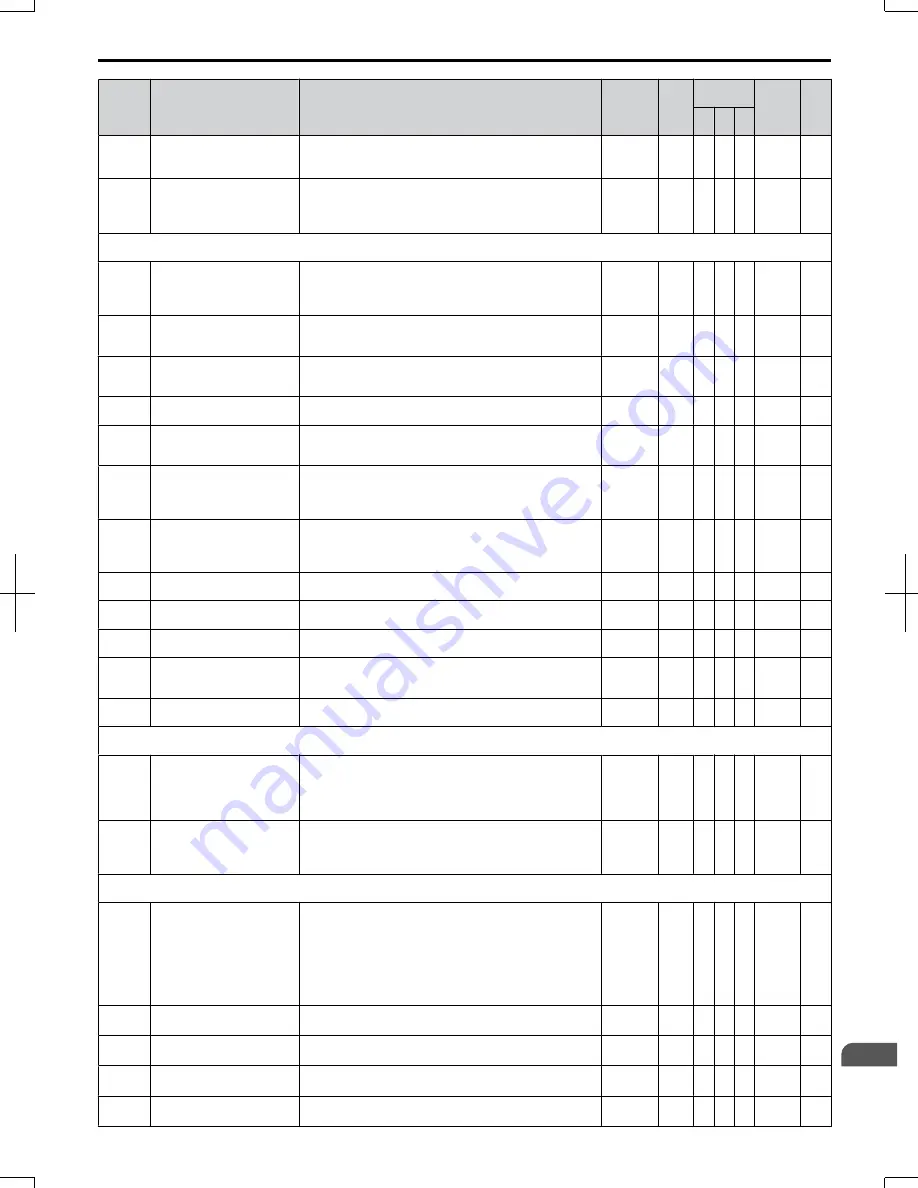
No.
Name
Description
Range
Def.
Control
Mode
Addr.
Hex
Pg.
V/f O
LV
P
M
b2-12
Short Circuit Brake Time at
Start
Sets the time for Short-Circuit brake operation at start.
Disabled when set to 0.00.
<32>
0.00 to
25.50
0.00 s − − A
1BA
110
b2-13
Short Circuit Brake Time at
Stop
Sets the Short-Circuit brake operation time at stop. Used to
stop a motor rotating due to inertia. Disabled when set to 0.00
seconds.
<32>
0.00 to
25.50
0.50 s − − A
1BB
110
b3: Speed Search
Use b3 parameters to configure Speed Search function operation.
b3-01
Speed Search Selection
Enables/disables the Speed Search function at start.
0: Disabled - Speed Search is not automatically performed at
start.
1: Enabled - Speed Search is automatically performed at start.
0 to 1
0
A A A
191
113
b3-02
Speed Search Deactivation
Current
Sets the current level at which the speed is assumed to be
detected and Speed Search is ended. Set as a percentage of
the drive rated current.
0 to 200
120
<2>
A A −
192
113
b3-03
Speed Search Deceleration
Time
Sets the time constant used to reduce the output frequency
during Speed Search. Related to a change from max. output
frequency to 0.
0.1 to 10.0 2.0 s A A −
193
113
b3-05
Speed Search Delay Time
Delays the Speed Search operation after a momentary power
loss to allow time for an external output contactor to close. 0.0 to 100 0.2 s A A A
195
113
b3-06
Output Current 1 during
Speed Search
Sets the current injected to the motor at the beginning of
Estimation type Speed Search. Set as a factor of the motor
rated current.
0.0 to 2.0
<12>
A A −
196
114
b3-10
Speed Search Detection
Compensation Gain
Sets the gain which is applied to the speed detected by Speed
Estimation Speed Search before the motor is reaccelerated.
Increase this setting if ov occurs when performing Speed
Search.
1.00 to
1.20
1.05 A A −
19A
114
b3-14
Bi-Directional Speed Search
Selection
Selects if Speed Search detects the motor rotation direction
during Speed Search.
0: Disabled–Frequency reference direction used
1: Enabled–Detected direction used
0,1
0
A A −
19E
114
b3-17
Speed Search Restart Current
Level
Sets the Speed Search restart current level as a percentage of
the drive rated current.
0 to 200 150% A A −
1F0
114
b3-18
Speed Search Restart
Detection Time
Sets the time in seconds for Speed Search restart to be
detected.
0.00 to
1.00
0.10 s A A −
1F1
114
b3-19
Number of Speed Search
Restarts
Sets the number of restarts possible for Speed Search restart
operations.
0 to 10
3
A A −
1F2
114
b3-24
Speed Search Method
Selection
Sets the Speed Search detection mode.
0: Current Detection Type
1: Speed Estimation Type
0,1
0
A A −
1C0
114
b3-25
Speed Search Retry Interval
Time
Sets the wait time before Speed Search restarts.
0 to 30.0 0.5 s A A A
1C8
115
b4: Timer Function
Use b4 parameters to configure timer function operation.
b4-01
Timer Function On-Delay
Time
Used in conjunction with a multi-function digital input (H1-
= 18) and a multi-function digital output (H2-
= 12)
programmed for the timer function. This sets the amount of
time between digital input closure and digital output
activation.
0.0 to
300.0
0.0 s A A A
1A3
115
b4-02
Timer Function Off-Delay
Time
Used in conjunction with a multi-function digital input (H1-
= 18) and a multi-function digital output programmed
for the timer function. This sets the amount of time the output
remains activated after the digital input is opened.
0.0 to
300.0
0.0 s A A A
1A4
115
b5: PID Control
Use b5 parameters to configure the PID control drive function.
b5-01 PID Function Setting
Sets the PID control mode.
0: Disabled
1: Enable (PID output = freq. ref., PID input is D-controlled)
2: (PID output = freq. ref., PID feedback is D-controlled)
3: Enable (PID output added to freq. ref., PID input is D-
controlled)
4: Enable (PID output added to freq. ref., PID feedback is D-
controlled)
0 to 4
0
A A A
1A5
118
b5-02
<22>
Proportional Gain Setting
(P)
Sets the proportional gain of the PID controller. A setting of
0.00 disables P control.
0.00 to
25.00
1.00 A A A
1A6
118
b5-03
<22>
Integral Time Setting (I)
Sets the integral time for the PID controller. A setting of 0.0
s disables integral control.
0.0 to
360.0
1.0 s A A A
1A7
118
b5-04
<22>
Integral Limit Setting
Sets the maximum output possible from the integrator.
0.0 to
100.0
100.0
%
A A A
1A8
118
b5-05
<22>
Derivative Time (D)
Sets D control derivative time. A setting of 0.00 s disables
derivative control.
0.00 to
10.00
0.00 s A A A
1A9
118
B.2 Parameter Table
SIEP C710606 20 OYMC AC Drive - V1000 User Manual
301
B
Parameter List
7/16/2008-13:23
Содержание V1000
Страница 11: ...Table of Contents This Page Intentionally Blank 10 SIEP C710606 20 OYMC AC Drive V1000 User Manual ...
Страница 27: ...1 4 Component Names This Page Intentionally Blank 26 SIEP C710606 20 OYMC AC Drive V1000 User Manual ...
Страница 37: ...2 2 Mechanical Installation This Page Intentionally Blank 36 SIEP C710606 20 OYMC AC Drive V1000 User Manual ...
Страница 63: ...3 12 Wiring Checklist This Page Intentionally Blank 62 SIEP C710606 20 OYMC AC Drive V1000 User Manual ...
Страница 221: ...5 11 U Monitor Parameters This Page Intentionally Blank 220 SIEP C710606 20 OYMC AC Drive V1000 User Manual ...
Страница 273: ...7 5 Drive Replacement This Page Intentionally Blank 272 SIEP C710606 20 OYMC AC Drive V1000 User Manual ...
Страница 287: ...8 6 Connecting an Option Card This Page Intentionally Blank 286 SIEP C710606 20 OYMC AC Drive V1000 User Manual ...
Страница 297: ...A 6 Drive Derating Data This Page Intentionally Blank 296 SIEP C710606 20 OYMC AC Drive V1000 User Manual ...
Страница 379: ...C 13 Self Diagnostics This Page Intentionally Blank 378 SIEP C710606 20 OYMC AC Drive V1000 User Manual ...
Страница 409: ...Index This Page Intentionally Blank 408 SIEP C710606 20 OYMC AC Drive V1000 User Manual ...
Страница 410: ...This Page Intentionally Blank SIEP C710606 20 OYMC AC Drive V1000 User Manual 409 ...


