Outputting Data and Controlling Operation through EtherNet/IP
FQ2 User’s Manual
285
C
onne
cti
ng th
rough
Ethern
et
9
FQ2 Communications for EtherNet/IP Connections
You can use EtherNet/IP tag data links to communicate between the PLC and the Vision Sensor to perform
control via command/response communications or to output data after measurements.
The FQ2 complies with EtherNet/IP conformance test version A8.
To connect to OMRON Controllers and communicate through EtherNet/IP, you use the Network Configurator to
set up tag data links (i.e., tags, tag sets, and connection settings).
Refer to the following manuals for details on the tag data link settings that are made with the Network
Configurator.
• NJ-series CPU Unit Built-in EtherNet/IP Port User’s Manual (Cat. No. W506)
• CS/CJ-series EtherNet/IP Units Operation Manual (Cat. No. W465)
• CJ-series EtherNet/IP Units Operation Manual for NJ-series CPU Unit (Cat. No. W495)
Types of Communications
●
Command/Response Communications
With EtherNet/IP communications, cyclic tag data link communications are performed with the connections that
are set between the PLC and Vision Sensor.
Command/response control signals are handled by storing control commands from the PLC to the Vision
Sensor and responses from the Vision Sensor to the PLC in the I/O memory of the PLC.
This allows you to control the operation of the Vision Sensor (e.g., perform continuous measurements or
change the scene) without using special communications instructions.
• Input Connection to Sensor (PLC to Vision Sensor)
The commands that are stored in the I/O memory of the PLC are sent to the Vision Sensor.
• Output Connection to PLC (Vision Sensor to PLC)
Responses from the Vision Sensor to the control commands are stored in the PLC I/O memory addresses or vari-
ables that are specified for the response area.
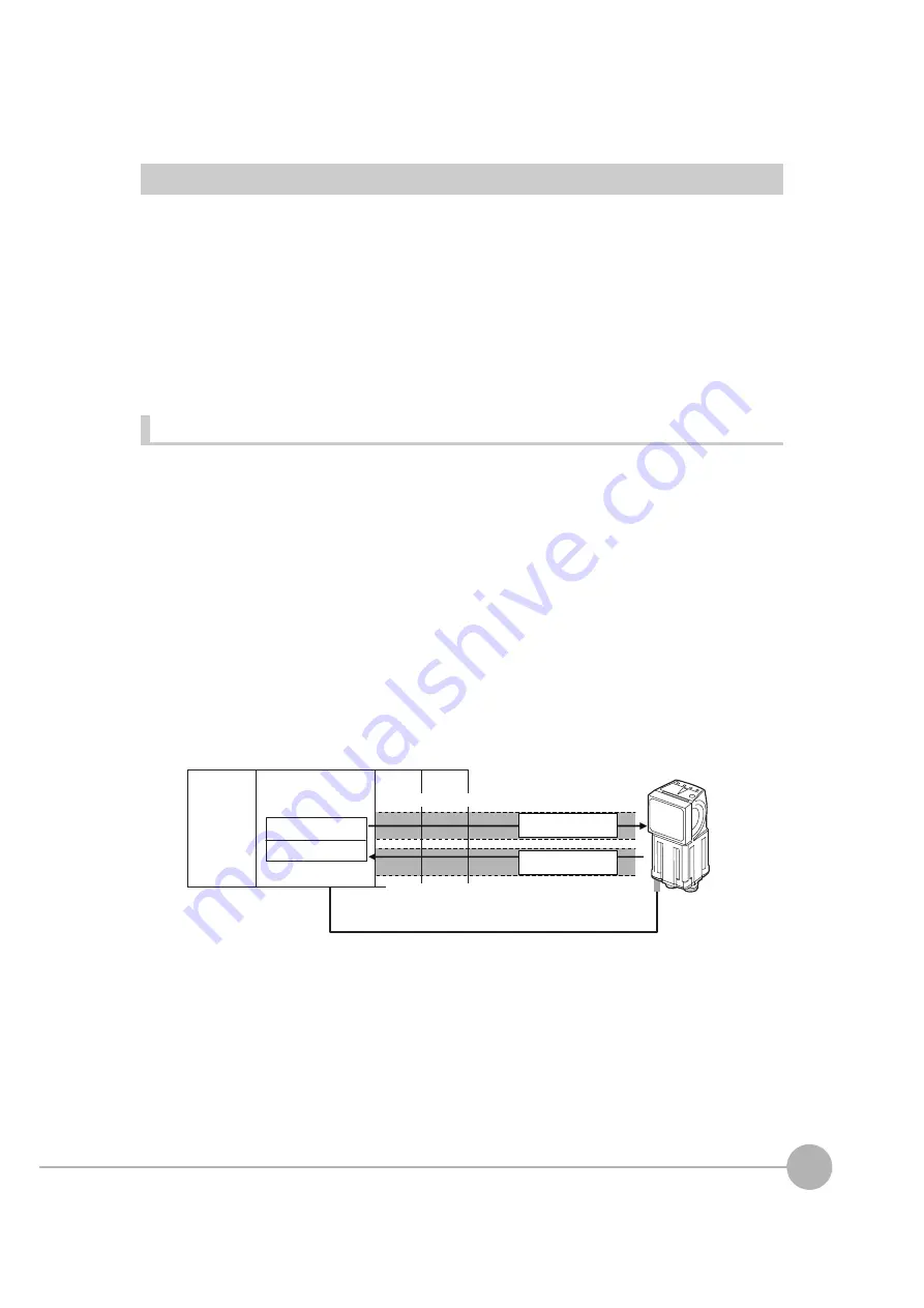
To send a control command, you write a control command to the command area (i.e., a variable or I/O memory
address in the PLC) that is specified for the output tag, and then turn ON the Command Execution (EXE) Bit.
As a result, the control command is sent through the input connection from the PLC to the Vision Sensor.
A control command does not need to be sent to execute measurements for the TRIG bit.
The measurement is executed simply by turning ON the TRIG bit.
The Vision Sensor executes the control command and sends a response back to the PLC through the output
connection from the Vision Sensor to the PLC.
The PLC stores the response in the response area (i.e., I/O memory addresses or variable) that is specified for
the input tag in the PLC.
PLC
V
ision Sensor
Command area
Response area
I/O memory or
v
aria
b
les
(comm
u
nications areas)
CPU Unit
Ether
N
et/IP (tag data links)
OK, etc.
• Contin
u
o
u
s meas
u
rements
• S
w
itching the scene n
u
m
b
er, etc.
Command
Response
Inp
u
t connection to Sensor
O
u
tp
u
t connection to PLC
Содержание FQ2 Series
Страница 1: ...User s Manual Smart Camera FQ2 Cat No Z326 E1 01A ...
Страница 58: ...Setting Up Ethernet 56 FQ2 User s Manual MEMO ...
Страница 90: ...Adjusting the Images That Were Taken 88 FQ2 User s Manual MEMO ...
Страница 190: ...Adjusting Judgement Parameters during Operation 188 FQ2 User s Manual MEMO ...
Страница 234: ...Functions Related to the System 232 FQ2 User s Manual MEMO ...
Страница 392: ...Controlling Operation and Outputting Data with FINS TCP No protocol Commands 390 FQ2 User s Manual MEMO ...
Страница 398: ...Controlling Operation and Outputting Data with RS 232C No protocol Communications 396 FQ2 User s Manual ...
Страница 399: ...11 Troubleshooting Troubleshooting 11 1 Error Histories 398 11 2 Error Messages 400 11 3 Basic Troubleshooting 401 ...
Страница 404: ...Basic Troubleshooting 402 FQ2 User s Manual MEMO ...
Страница 513: ...Index FQ2 User s Manual 511 Index 12 ...
Страница 515: ......