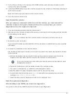

All commands in the diagnostic procedures are issued from the node where the component is being replaced.
1. If the node to be serviced is not at the LOADER prompt, perform the following steps:
a. Select the Maintenance mode option from the displayed menu.
b. After the node boots to Maintenance mode, halt the node:
halt
After you issue the command, you should wait until the system stops at the LOADER prompt.
During the boot process, you can safely respond
y
to prompts:
▪
A prompt warning that when entering Maintenance mode in an HA configuration, you must ensure
that the healthy node remains down.
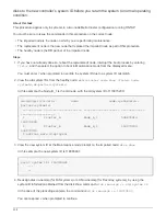
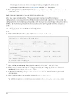
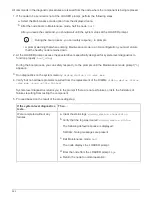
2. At the LOADER prompt, access the special drivers specifically designed for system-level diagnostics to
function properly:
boot_diags
During the boot process, you can safely respond
y
to the prompts until the Maintenance mode prompt (*>)
appears.
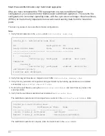
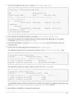
3. Run diagnostics on the system memory:
sldiag device run -dev mem
4. Verify that no hardware problems resulted from the replacement of the DIMMs:
sldiag device status
-dev mem -long -state failed
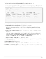
System-level diagnostics returns you to the prompt if there are no test failures, or lists the full status of
failures resulting from testing the component.
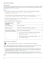
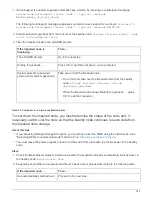
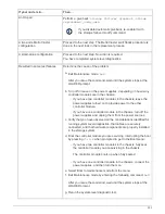
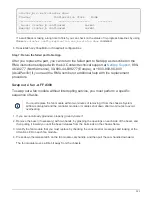
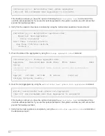
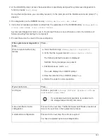
5. Proceed based on the result of the preceding step:
If the system-level diagnostics
tests…
Then…
Were completed without any
failures
a. Clear the status logs:
sldiag device clearstatus
b. Verify that the log was cleared:
sldiag device status
The following default response is displayed:
SLDIAG: No log messages are present.
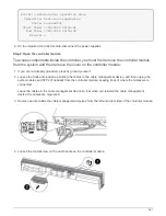
c. Exit Maintenance mode:
halt
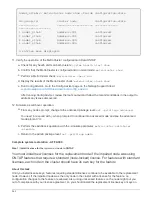
The node displays the LOADER prompt.
d. Boot the node from the LOADER prompt:
bye
e. Return the node to normal operation:
352
Содержание AFF A700
Страница 4: ...AFF and FAS System Documentation 1...
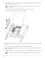
Страница 208: ...3 Close the controller module cover and tighten the thumbscrew 205...
Страница 248: ...2 Close the controller module cover and tighten the thumbscrew 245...
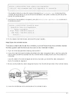
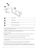
Страница 308: ...Power supply Cam handle release latch Power and Fault LEDs Cam handle 305...
Страница 381: ...Power supply Cam handle release latch Power and Fault LEDs Cam handle 378...
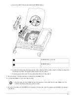
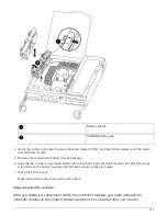
Страница 437: ...1 Locate the DIMMs on your controller module 434...
Страница 601: ...Cabling SAS shelves in FAS9000 AFF A700 and ASA AFF A700 ONTAP 9 8 and later Cabling SAS storage ONTAP 9 8 and later 598...
Страница 605: ...602...
Страница 1117: ...3 Close the controller module cover and tighten the thumbscrew 1114...
Страница 1157: ...2 Close the controller module cover and tighten the thumbscrew 1154...
Страница 1228: ...Power supply Cam handle release latch Power and Fault LEDs Cam handle 1225...
Страница 1300: ...Power supply Cam handle release latch Power and Fault LEDs Cam handle 1297...
Страница 1462: ...Installing SuperRail to round hole four post rack 1459...
Страница 1602: ...1599...
Страница 1630: ...1627...
Страница 1634: ...Orange ring on horizontal bracket Cable chain 1631...
Страница 1637: ...b Raise the drive handle to vertical c Use the handle to lift the drive from the drive drawer 1634...
Страница 1643: ...Callout Cable chain Connector Connects to Left Vertical Midplane Left Horizontal Drive drawer 1640...
Страница 1645: ...Guide rail 1642...
Страница 1648: ...Tab that you press to release the fan module handle 5 Use the fan module handle to pull the fan module out of the shelf 1645...
Страница 1669: ...Attention LED light on 1666...