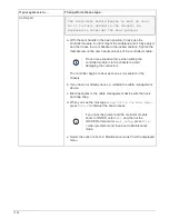

It is important that you apply the commands in the steps on the correct systems:
• The
replacement
node is the new node that replaced the impaired node as part of this procedure.
• The
healthy
node is the HA partner of the
replacement
node
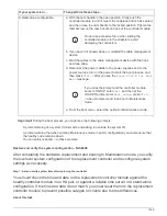
Steps
1. If the
replacement
node is not at the LOADER prompt, halt the system to the LOADER prompt.
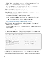
2. On the healthy node, check the system time:
show date
The date and time are given in GMT.
3. At the LOADER prompt, check the date and time on the
replacement
node:
show date
The date and time are given in GMT.
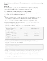
4. If necessary, set the date in GMT on the replacement node:
set date
mm/dd/yyyy
5. If necessary, set the time in GMT on the replacement node:
set time
hh:mm:ss
6. At the LOADER prompt, confirm the date and time on the
replacement
node:
show date
The date and time are given in GMT.
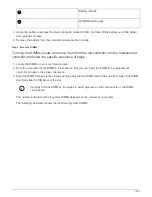
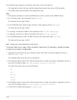
Step 2: Verify and set the HA state of the controller module
You must verify the
HA
state of the controller module and, if necessary, update the state
to match your system configuration.
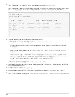
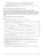
1. In Maintenance mode from the new controller module, verify that all components display the same
HA
state:
ha-config show
The HA state should be the same for all components.
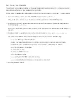
2. If the displayed system state of the controller module does not match your system configuration, set the
HA
state for the controller module:
ha-config modify controller ha-state
The value for HA-state can be one of the following:
◦
ha
◦
mcc
◦
mcc-2n
◦
mccip
◦
non-ha
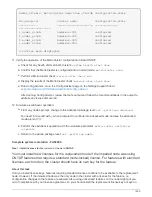
3. If the displayed system state of the controller module does not match your system configuration, set the
HA
state for the controller module:
ha-config modify controller ha-state
4. Confirm that the setting has changed:
ha-config show
1250
Содержание AFF A700
Страница 4: ...AFF and FAS System Documentation 1...
Страница 208: ...3 Close the controller module cover and tighten the thumbscrew 205...
Страница 248: ...2 Close the controller module cover and tighten the thumbscrew 245...
Страница 308: ...Power supply Cam handle release latch Power and Fault LEDs Cam handle 305...
Страница 381: ...Power supply Cam handle release latch Power and Fault LEDs Cam handle 378...
Страница 437: ...1 Locate the DIMMs on your controller module 434...
Страница 601: ...Cabling SAS shelves in FAS9000 AFF A700 and ASA AFF A700 ONTAP 9 8 and later Cabling SAS storage ONTAP 9 8 and later 598...
Страница 605: ...602...
Страница 1117: ...3 Close the controller module cover and tighten the thumbscrew 1114...
Страница 1157: ...2 Close the controller module cover and tighten the thumbscrew 1154...
Страница 1228: ...Power supply Cam handle release latch Power and Fault LEDs Cam handle 1225...
Страница 1300: ...Power supply Cam handle release latch Power and Fault LEDs Cam handle 1297...
Страница 1462: ...Installing SuperRail to round hole four post rack 1459...
Страница 1602: ...1599...
Страница 1630: ...1627...
Страница 1634: ...Orange ring on horizontal bracket Cable chain 1631...
Страница 1637: ...b Raise the drive handle to vertical c Use the handle to lift the drive from the drive drawer 1634...
Страница 1643: ...Callout Cable chain Connector Connects to Left Vertical Midplane Left Horizontal Drive drawer 1640...
Страница 1645: ...Guide rail 1642...
Страница 1648: ...Tab that you press to release the fan module handle 5 Use the fan module handle to pull the fan module out of the shelf 1645...
Страница 1669: ...Attention LED light on 1666...