29-81
MPC8260 PowerQUICC II UserÕs Manual
MOTOROLA
Part IV. Communications Processor Module
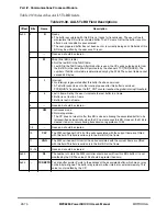
Table 29-42 describes interrupt queue entry Þelds.
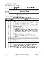
29.11.3 Interrupt Queue Parameter Tables
The interrupt queue parameters are held in parameter tables in the dual-port RAM; see
Table 29-43. INTT_BASE in the parameter RAM points to the base address of these tables.
Each of the four interrupt queues has its own parameter table with a starting address given
by IN RCT/TCT[INTQ]
´
16.
Table 29-42. Interrupt Queue Entry Field Description
Offset Bits
Name
Description
0x00
0
V
Valid interrupt entry
0 This interrupt queue entry is free and can be use by the CP.
1 This interrupt queue entry is valid. The host should read this interrupt and clear this bit.
1
Ñ
Reserved, should be cleared.
2
W
Wrap bit. When set, this is the last interrupt circular table entry. During initialization, the
host must clear all W bits in the table except the last one, which must be set.
3Ð10
Ñ
Reserved, should be cleared.
11
TBNR
Tx buffer-not-ready. Set when a transmit buffer-not-ready interrupt is issued. This interrupt
is issued when the CP tries to open a TxBD that is not ready (R = 0). This interrupt is sent
only if TCT[BNM] = 1. This interrupt has an associated channel code.
Note that for AAL5, this interrupt is sent only if frame transmission is started. In this case,
an abort frame transmission is sent (last cell with length=0), the channel is taken out of the
APC, and the TCT[VCON] ßag is cleared.
12
RXF
Rx frame. RXF is set when an Rx frame interrupt is issued. This interrupt is issued at the
end of AAL5 PDU reception. This interrupt is issued only if RCT[RXFM] = 1. This interrupt
has an associated channel code.
13
BSY
Busy condition. The BD table or the free buffer pool associated with this channel is busy.
Cells were discarded due to this condition. This interrupt has an associated channel code.
14
TXB
Tx buffer. TXB is set when a transmit buffer interrupt is issued. This interrupt is enabled
when both TxBD[I] and TCT[IMK] = 1. This interrupt has an associated channel code.
15
RXB
Rx buffer. RXB is set when an Rx buffer interrupt is issued. This interrupt is enabled when
both RxBD[I] and RCT[RXBM] = 1. This interrupt has an associated channel code.
0x02
Ñ
CC
Channel code speciÞes the channel associated with this interrupt.
Table 29-43. Interrupt Queue Parameter Table
Offset
1
Name
Width
Description
0x00
INTQ_BASE
Word
Base address of the interrupt queue. User-deÞned.
0x04
INTQ_PTR
Word
Pointer to interrupt queue entry. Initialize to INTQ_BASE.
0x08
INT_CNT
Half Word Interrupt counter. Initialize with INT_ICNT. The CP decrements INT_CNT for
each interrupt. When INT_CNT reaches zero, the queueÕs global interrupt ßag
FCCE[GINT
x
] is set.
0x0A
INT_ICNT
Half Word Interrupt initial count. User-deÞned global interrupt thresholdÑthe number of
interrupts required before the CP issues a global interrupt (FCCE[GINT
x
]).
Содержание MPC8260 PowerQUICC II
Страница 1: ...MPC8260UM D 4 1999 Rev 0 MPC8260 PowerQUICC II UserÕs Manual ª ª ...
Страница 32: ...xxxii MPC8260 PowerQUICC II UserÕs Manual MOTOROLA CONTENTS Paragraph Number Title Page Number ...
Страница 66: ...lxvi MPC8260 PowerQUICC II UserÕs Manual MOTOROLA ...
Страница 88: ...1 18 MPC8260 PowerQUICC II UserÕs Manual MOTOROLA Part I Overview ...
Страница 120: ...2 32 MPC8260 PowerQUICC II UserÕs Manual MOTOROLA Part I Overview ...
Страница 138: ...Part II iv MPC8260 PowerQUICC II UserÕs Manual MOTOROLA Part II Configuration and Reset ...
Страница 184: ...4 46 MPC8260 PowerQUICC II UserÕs Manual MOTOROLA Part II ConÞguration and Reset ...
Страница 202: ...Part III vi MPC8260 PowerQUICC II UserÕs Manual MOTOROLA Part III The Hardware Interface ...
Страница 266: ...8 34 MPC8260 PowerQUICC II UserÕs Manual MOTOROLA Part III The Hardware Interface ...
Страница 382: ...10 106 MPC8260 PowerQUICC II UserÕs Manual MOTOROLA Part III The Hardware Interface ...
Страница 392: ...11 10 MPC8260 PowerQUICC II UserÕs Manual MOTOROLA Part III The Hardware Interface ...
Страница 430: ...Part IV viii MOTOROLA Part IV Communications Processor Module ...
Страница 490: ...14 36 MPC8260 PowerQUICC II UserÕs Manual MOTOROLA Part IV Communications Processor Module ...
Страница 524: ...17 10 MPC8260 PowerQUICC II UserÕs Manual MOTOROLA Part IV Communications Processor Module ...
Страница 556: ...18 32 MPC8260 PowerQUICC II UserÕs Manual MOTOROLA Part IV Communications Processor Module ...
Страница 584: ...19 28 MPC8260 PowerQUICC II UserÕs Manual MOTOROLA Part IV Communications Processor Module ...
Страница 632: ...21 24 MPC8260 PowerQUICC II UserÕs Manual MOTOROLA Part IV Communications Processor Module ...
Страница 652: ...22 20 MPC8260 PowerQUICC II UserÕs Manual MOTOROLA Part IV Communications Processor Module ...
Страница 668: ...23 16 MPC8260 PowerQUICC II UserÕs Manual MOTOROLA Part IV Communications Processor Module ...
Страница 758: ...27 28 MPC8260 PowerQUICC II UserÕs Manual MOTOROLA Part IV Communications Processor Module ...
Страница 780: ...28 22 MPC8260 PowerQUICC II UserÕs Manual MOTOROLA Part IV Communications Processor Module ...
Страница 874: ...29 94 MPC8260 PowerQUICC II UserÕs Manual MOTOROLA Part IV Communications Processor Module ...
Страница 920: ...31 18 MPC8260 PowerQUICC II UserÕs Manual MOTOROLA Part IV Communications Processor Module ...
Страница 980: ...A 4 MPC8260 PowerQUICC II UserÕs Manual MOTOROLA Appendixes ...
Страница 1002: ...Index 22 MPC8260 PowerQUICC II UserÕs Manual MOTOROLA INDEX ...
Страница 1006: ......


