MOTOROLA
Chapter 20. SCC UART Mode
20-21
Part IV. Communications Processor Module
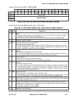
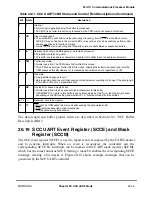
Table 20-12 describes SCCE Þelds for UART mode.
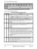
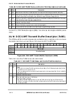
20.20 SCC UART Status Register (SCCS)
The SCC UART status register (SCCS), shown in Figure 20-12, monitors the real-time
status of RXD.
Table 20-12. SCCE/SCCM Field Descriptions for UART Mode
Bit
Name
Description
0Ð2 Ñ
Reserved, should be cleared.
3
GLR
Glitch on receive. Set when the SCC encounters an Rx clock glitch.
4
GLT
Glitch on transmit. Set when the SCC encounters a Tx clock glitch.
5
Ñ
Reserved, should be cleared.
6
AB
Autobaud. Set when an autobaud lock is detected. The core should rewrite the baud rate generator with
the precise divider value. See Chapter 16, ÒBaud-Rate Generators (BRGs).Ó
7
IDL
Idle sequence status changed. Set when the channel detects a change in the serial line. The lineÕs real-
time status can be read in SCCS[ID]. Idle is entered when a character of all ones is received; it is exited
when a zero is received.
8
GRA
Graceful stop complete. Set as soon as the transmitter Þnishes any buffer in progress after a
GRACEFUL
STOP
TRANSMIT
command is issued. It is set immediately if no buffer is in progress.
9
BRKE
Break end. Set when an idle bit is received after a break sequence.
10
BRKS
Break start. Set when the Þrst character of a break sequence is received. Multiple BRKS events are not
received if a long break sequence is received.
11
Ñ
Reserved, should be cleared.
12
CCR
Control character received and rejected. Set when a control character is recognized and stored in the
receive control character register RCCR.
13
BSY
Busy. Set when a character is received and discarded due to a lack of buffers. In multidrop mode, the
receiver automatically enters hunt mode; otherwise, reception continues when a buffer is available. The
latest point that an RxBD can be changed to empty and guarantee avoiding the busy condition is the
middle of the stop bit of the Þrst character to be stored in that buffer.
14
TX
Tx event. Set when a buffer is sent. If TxBD[CR] = 1, TX is set no sooner than when the last stop bit of
the last character in the buffer begins transmission. If TxBD[CR] = 0, TX is set after the last character is
written to the Tx FIFO. TX also represents a CTS lost error; check TxBD[CT].
15
RX
Rx event. Set when a buffer is received, which is no sooner than the middle of the Þrst stop bit of the
character that caused the buffer to close. Also represents a general receiver error (overrun, CD lost,
parity, idle sequence, and framing errors); the RxBD status and control Þelds indicate the speciÞc error.
Bit
0
1
2
3
4
5
6
7
Field
Ñ
ID
Reset
0000_0000_0000_0000
R/W
R
Addr
0x11A17 (SCCS1); 0x11A37 (SCCS2); 0x11A57 (SCCS3); 0x11A77 (SCCS4)
Figure 20-12. SCC Status Register for UART Mode (SCCS)
Содержание MPC8260 PowerQUICC II
Страница 1: ...MPC8260UM D 4 1999 Rev 0 MPC8260 PowerQUICC II UserÕs Manual ª ª ...
Страница 32: ...xxxii MPC8260 PowerQUICC II UserÕs Manual MOTOROLA CONTENTS Paragraph Number Title Page Number ...
Страница 66: ...lxvi MPC8260 PowerQUICC II UserÕs Manual MOTOROLA ...
Страница 88: ...1 18 MPC8260 PowerQUICC II UserÕs Manual MOTOROLA Part I Overview ...
Страница 120: ...2 32 MPC8260 PowerQUICC II UserÕs Manual MOTOROLA Part I Overview ...
Страница 138: ...Part II iv MPC8260 PowerQUICC II UserÕs Manual MOTOROLA Part II Configuration and Reset ...
Страница 184: ...4 46 MPC8260 PowerQUICC II UserÕs Manual MOTOROLA Part II ConÞguration and Reset ...
Страница 202: ...Part III vi MPC8260 PowerQUICC II UserÕs Manual MOTOROLA Part III The Hardware Interface ...
Страница 266: ...8 34 MPC8260 PowerQUICC II UserÕs Manual MOTOROLA Part III The Hardware Interface ...
Страница 382: ...10 106 MPC8260 PowerQUICC II UserÕs Manual MOTOROLA Part III The Hardware Interface ...
Страница 392: ...11 10 MPC8260 PowerQUICC II UserÕs Manual MOTOROLA Part III The Hardware Interface ...
Страница 430: ...Part IV viii MOTOROLA Part IV Communications Processor Module ...
Страница 490: ...14 36 MPC8260 PowerQUICC II UserÕs Manual MOTOROLA Part IV Communications Processor Module ...
Страница 524: ...17 10 MPC8260 PowerQUICC II UserÕs Manual MOTOROLA Part IV Communications Processor Module ...
Страница 556: ...18 32 MPC8260 PowerQUICC II UserÕs Manual MOTOROLA Part IV Communications Processor Module ...
Страница 584: ...19 28 MPC8260 PowerQUICC II UserÕs Manual MOTOROLA Part IV Communications Processor Module ...
Страница 632: ...21 24 MPC8260 PowerQUICC II UserÕs Manual MOTOROLA Part IV Communications Processor Module ...
Страница 652: ...22 20 MPC8260 PowerQUICC II UserÕs Manual MOTOROLA Part IV Communications Processor Module ...
Страница 668: ...23 16 MPC8260 PowerQUICC II UserÕs Manual MOTOROLA Part IV Communications Processor Module ...
Страница 758: ...27 28 MPC8260 PowerQUICC II UserÕs Manual MOTOROLA Part IV Communications Processor Module ...
Страница 780: ...28 22 MPC8260 PowerQUICC II UserÕs Manual MOTOROLA Part IV Communications Processor Module ...
Страница 874: ...29 94 MPC8260 PowerQUICC II UserÕs Manual MOTOROLA Part IV Communications Processor Module ...
Страница 920: ...31 18 MPC8260 PowerQUICC II UserÕs Manual MOTOROLA Part IV Communications Processor Module ...
Страница 980: ...A 4 MPC8260 PowerQUICC II UserÕs Manual MOTOROLA Appendixes ...
Страница 1002: ...Index 22 MPC8260 PowerQUICC II UserÕs Manual MOTOROLA INDEX ...
Страница 1006: ......

