APPENDIX
– Selection and Mounting of Encoder
189
It is preferred that a solid shaft extension is
specified from the motor manufacturer for a
length recommended by the encoder
manufacturer.
Although it is not the preferred method,
installations that employ a screwed on sub
shaft adapter should:
-
use the original hole used to machine the
motor shaft
-
use locktight to hold the thread in position
-
align the stub shaft to 0.002 inches TIR or
less with a dial indicator
A hub-shaft or hollow-shaft encoder should be
mounted so that its shaft receptacle is in as
close as possible alignment with the axis of the
motor shaft. Clamp or set screws should then
be tightened to secure the encoder.
REMEMBER: If you are following the preferred
method of insulating the encoder from the
motor, install the proper insulating hardware.
NOTE: Do not defeat or restrict the flexure.
This causes failure of the encoder or driving
shaft bearings.
Encoder Protective Covers
In order to protect the encoders from
mechanical damage, it is preferred that for
exposed encoders a mechanical protective
cover is used.
Encoders are vulnerable to mechanical
damage from impact. Encoders can be
damaged by impact during installation or
during exposed operation. Motors are even
sometimes lifted by the encoders on one end.
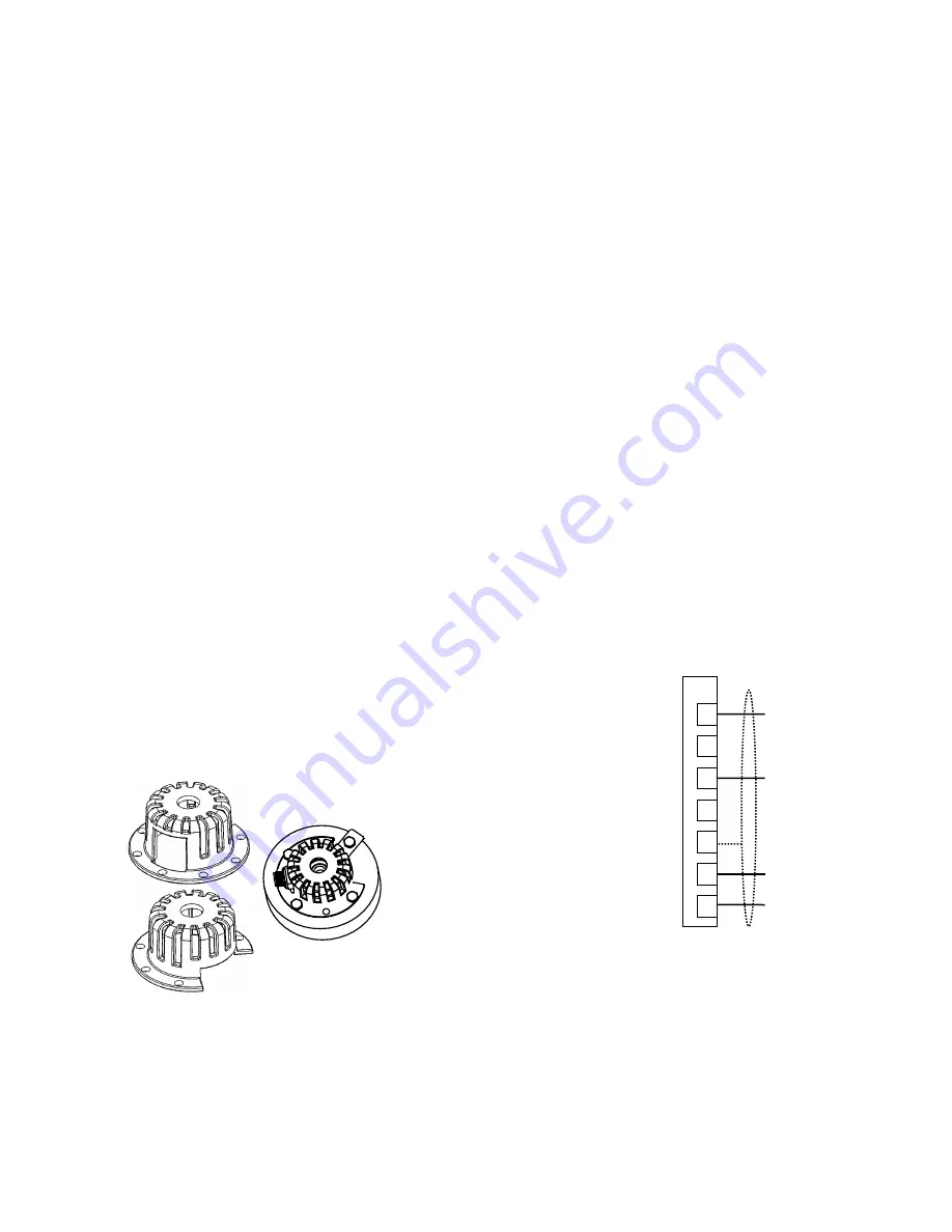
Therefore, it is preferred that the encoder be
protected by a cover as shown below.
Figure 55: Protective Encoder Covers
Differential Line Drivers
Use limited slew rate differential line drivers, in
order to minimize transmission line reflections
use type 7272 differential line drivers.
Encoder’s line drivers transition from logic
states in a fraction of a microsecond. The fast
rise and fall times of the driver
’s circuitry can
interact with the cable impedance and create
significant ringing on the receiver end of the
cable. This can interfere with the encoder
signals and the operation of the drive. To
reduce the ringing, it is recommended that the
encoder use type 7272 line drivers, which have
slower rise and fall times.
Differenetial line drivers are recommended to
improve performance. Line driver outputs
should use differential pairs of complementary
outputs, each paired with its inverse. This
allows the signal to be used with a differential
line receiver, which improves the noise margin,
cancels common-mode noise and helps to
reject ringing from the cable.
Single-Ended Encoders
Although not recommended due to the
absence of noise immunity, the HPV900 S2
drive can be configured to run with singled
ended encoders with setting of SW3 on page
190.
Figure 56: Single-Ended Encoder
Connection
1
2
3
4
5
17
18
A
/A
B
/B
shield
e5/12VDC power
encoder common
TB1
Содержание HPV 900 Series 2
Страница 4: ......
Страница 195: ...APPENDIX Dimensions Mounting Holes Weights 173 Figure 46 Frame 2 Dimensions Mounting Holes and Weight...
Страница 196: ...APPENDIX Dimensions Mounting Holes Weights 174 Figure 47 Frame 3 Dimensions Mounting Holes and Weight...
Страница 197: ...APPENDIX Dimensions Mounting Holes Weights 175 Figure 48 Frame 3 5 Dimensions Mounting Holes and Weight...
Страница 198: ...APPENDIX Dimensions Mounting Holes Weights 176 Figure 49 Frame 4 Dimensions Mounting Holes and Weight...
Страница 199: ...APPENDIX Dimensions Mounting Holes Weights 177 Figure 50 Frame 5 Dimensions Mounting Holes and Weight...
Страница 227: ...205 Z Z MARKER LOST 150 Zero Speed Level parameter 47 Zero Speed logic output 105 Zero Speed Time parameter 47...
Страница 228: ......
Страница 229: ......


