User Switches C1 Submenu
97
The inner loop crossover parameter (INNER
LOOP XOVER(A1)) should not need to be
changed. But if the number is changed, it
must satisfy the following formula:
multiplier
reduce
gain
response
crossover
loop
inner
PI Speed Regulator
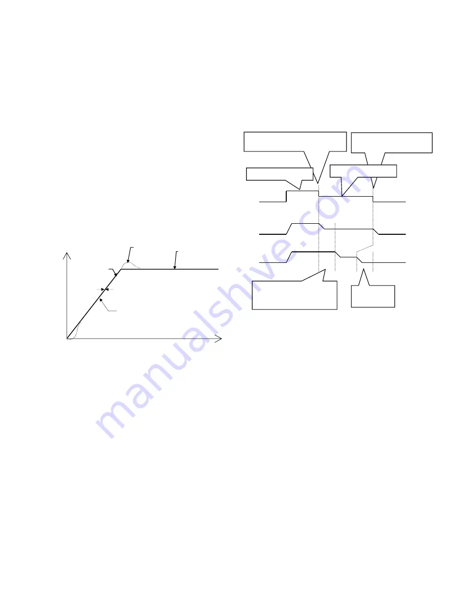
When the Proportional plus Integral (PI) speed
regulator is used, the response to a speed
reference is different. As an example, the PI
Speed Regulator’s speed response is shown
below for a ramped speed reference. With the
PI speed regulator, the end of each accel and
decel period, there will be an overshoot. The
amount of overshoot will be a function of the
defined phase margin and response
parameters.
Because of this overshoot, the PI regulator is
not recommended for elevator control
PI Speed Regulator Example
The PI Speed Regulator is tuned by:
System Inertia parameter (INERTIA(A1)),
which is easy to obtain by using the drive
software to estimate the system inertia.
Response parameter
(RESPONSE(A1)), which is the overall
regulator bandwidth in radians per sec.
This parameter defines the
responsiveness of the speed regulator.
Speed Phase Margin parameter (SPD
PHASE MARGIN(A1)) is used only by
the PI Speed Regulator to define the
phase margin of the speed regulator.
MULTI-STEP COMMAND DELAYS
When setting up an elevator, slow-down and
stop switches are set at fixed locations in the
shaft. Once the drive is tuned, it might require
the user to move the switches in the shaft in
order to minimize the time spent at leveling
speed.
Under "normal” operation, the drive speed
reference follows the speed command. By
configuring for “delayed” operation and setting
speed command 1 for a delay (MLT-SPD TO
DLY 1 = MSPD 1), the recognition of the speed
command change from speed command 1 to
any other speed command (in this case speed
command 2) will be delayed by the setting of
MSPD DELAY 1 (A1) parameter.
Phase Loss Check
(Phase Loss Check Selection)
This parameter allows the user to select the
sensitivity of the phase loss detection.
DISABLED: Phase loss checking is
completely disabled; an open phase
will not be detected. Drive will keep
running at single phase but greatly
derated.
LOW SENS: Phase loss detection is
done with low sensitivity. The phase
loss condition must persist for twice as
long as in the HIGH SENS setting.
This allows for more bus voltage
ripple.
HIGH SENS: Phase loss detection is
done with high sensitivity. Phase loss
is declared faster at higher
frequency
motor current than at lower
frequencies. This is the default setting.
speed
feedback
zero tracking delay
speed
reference
commanded
speed
overshoot
time
speed
Speed Command 2 commanded
(Slow down switch activated)
Speed Command 1
delay time = 0.3 sec
(MSPD DELAY 1 = 0.3 sec)
Speed Command 1
Zero speed commanded
(Stop switch activated)
Travel time
saved
speed
command
speed
reference
(normal)
speed
reference
(delayed)
Speed Command 2
Содержание HPV 900 Series 2
Страница 4: ......
Страница 195: ...APPENDIX Dimensions Mounting Holes Weights 173 Figure 46 Frame 2 Dimensions Mounting Holes and Weight...
Страница 196: ...APPENDIX Dimensions Mounting Holes Weights 174 Figure 47 Frame 3 Dimensions Mounting Holes and Weight...
Страница 197: ...APPENDIX Dimensions Mounting Holes Weights 175 Figure 48 Frame 3 5 Dimensions Mounting Holes and Weight...
Страница 198: ...APPENDIX Dimensions Mounting Holes Weights 176 Figure 49 Frame 4 Dimensions Mounting Holes and Weight...
Страница 199: ...APPENDIX Dimensions Mounting Holes Weights 177 Figure 50 Frame 5 Dimensions Mounting Holes and Weight...
Страница 227: ...205 Z Z MARKER LOST 150 Zero Speed Level parameter 47 Zero Speed logic output 105 Zero Speed Time parameter 47...
Страница 228: ......
Страница 229: ......


