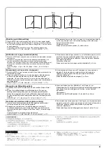
1
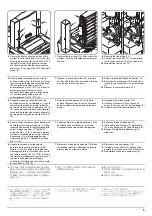
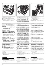
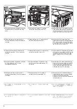
A
B
C
D
E
F
G
H
付属品
A パンチユニット...................... 1
B パンチ基板.......................... 1
C 電線................................ 1
D パンチくずボックス.................. 1
E ガイド.............................. 1
F ビス M4 × 8 タップタイト S .......... 1
G ビス M4 × 10 タップタイト S ......... 2
H ラベル ............................. 1
付属品に固定テープ、緩衝材が付いている場合
は必ず取り外すこと。
Supplied parts
A Hole punch unit........................................ 1
B Punch PCB .............................................. 1
C Power cord .............................................. 1
D Waste hole punch box ............................. 1
E Guide ....................................................... 1
F M4 × 8 tap Tight S screw ......................... 1
G M4 × 10 tap Tight S screw ....................... 2
H Label ........................................................ 1
Be sure to remove any fixing tapes or cushion-
ing material attached to the supplied parts.
Pièces fournies
A Perforatrice .............................................. 1
B Carte de perforation................................. 1
C Cordon d’alimentation.............................. 1
D Bac de récupération de la perforatrice .... 1
E Guide ....................................................... 1
F Vis S taraudée M4 × 8 ............................. 1
G Vis S taraudée M4 × 10 ........................... 2
H Etiquette................................................... 1
Veiller à retirer toute bande de fixation ou
matériau d’emballage entourant les pièces
fournies.
Partes suministradas
A Perforadora.............................................. 1
B PCB de perforación ................................. 1
C Cable de alimentación ............................. 1
D Caja para desechos de la perforación ..... 1
E Guía......................................................... 1
F Tornillo de ajuste M4 × 8.......................... 1
G Tornillo de ajuste M4 × 10........................ 2
H Etiqueta.................................................... 1
Asegúrese de quitar cualquier cinta de fijación
o material de amortiguación colocado en las
partes suministradas.
Gelieferte Teile
A Lochereinheit ........................................... 1
B Locherplatine ........................................... 1
C Netzkabel................................................. 1
D Lochungsabfallbehälter ........................... 1
E Führung ................................................... 1
F M4 × 8 Passstift-Verbundschrauben........ 1
G M4 × 10 Passstift-Verbundschrauben...... 2
H Aufkleber.................................................. 1
Sicherstellen, dass sämtliche Klebebänder
und Dämpfungsmaterialien von den geliefer-
ten Teilen entfernt werden.
Parti fornite
A Unità di perforazione ............................... 1
B Scheda a circuiti stampati di perforazione .. 1
C Cavo di alimentazione ............................. 1
D Scarto perforazione ................................. 1
E Guida ....................................................... 1
F Viti con testa a croce S M4 × 8 ................ 1
G Viti con testa a croce S M4 × 10 .............. 2
H Etichetta................................................... 1
Assicurarsi di rimuovere qualsiasi nastro ade-
sivo o imbottitura fissati alle parti fornite.
Italiano
Deutsch
Español
Français
English
Содержание TASKalfa 420i
Страница 1: ...SERVICE MANUAL Published in May 2010 842KS113 2KSSM063 Rev 3 TASKalfa 420i TASKalfa 520i ...
Страница 4: ...This page is intentionally left blank ...
Страница 10: ...This page is intentionally left blank ...
Страница 14: ...2KR 2KS This page is intentionally left blank ...
Страница 224: ...2KR 2KS 1 4 66 This page is intentionally left blank ...
Страница 328: ...2KR 2KS 2 3 30 This page is intentionally left blank ...
Страница 371: ...INSTALLATION GUIDE FOR PAPER FEEDER ...
Страница 381: ...INSTALLATION GUIDE FOR 3000 SHEETS PAPER FEEDER ...
Страница 436: ...INSTALLATION GUIDE FOR CENTER FOLDING UNIT ...
Страница 450: ...INSTALLATION GUIDE FOR MAILBOX ...
Страница 458: ...INSTALLATION GUIDE FOR HOLE PUNCH UNIT ...
Страница 470: ...INSTALLATION GUIDE FOR BUILT IN FINISHER ...
Страница 483: ...INSTALLATION GUIDE FOR JOB SEPARATOR ...
Страница 491: ...INSTALLATION GUIDE FOR FAX System ...
Страница 507: ......
Страница 508: ......


