2KR/2KS
1-2-15
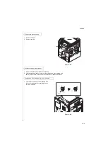
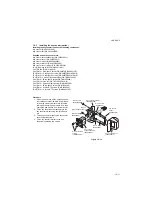
18. Connect the connector of the key counter
signal cable to the connector of the key
counter wire.
19. Fit the key counter cover with the key
counter socket assembly inserted to the key
counter cover retainer using the M4 x 6
screw.
20. Insert the key counter into the key counter
socket assembly.
Figure 1-2-21
21. Turn the main power switch on and enter the
maintenance mode.
22. Run maintenance item U204 and select
[KEY COUNTER].
23. Exit the maintenance mode.
24. Check that the message requesting the key
counter to be inserted is displayed on the
touch panel when the key counter is pulled
out.
25. Check that the counter counts up as prints
are made.
B1
A2
DP
OPT1
Key counter wire
M4 x 6 screw
(B4A04060)
Key counter
signal cable
Connectors
Key conuter cover
Key counter
cover retainer
Содержание TASKalfa 420i
Страница 1: ...SERVICE MANUAL Published in May 2010 842KS113 2KSSM063 Rev 3 TASKalfa 420i TASKalfa 520i ...
Страница 4: ...This page is intentionally left blank ...
Страница 10: ...This page is intentionally left blank ...
Страница 14: ...2KR 2KS This page is intentionally left blank ...
Страница 224: ...2KR 2KS 1 4 66 This page is intentionally left blank ...
Страница 328: ...2KR 2KS 2 3 30 This page is intentionally left blank ...
Страница 371: ...INSTALLATION GUIDE FOR PAPER FEEDER ...
Страница 381: ...INSTALLATION GUIDE FOR 3000 SHEETS PAPER FEEDER ...
Страница 436: ...INSTALLATION GUIDE FOR CENTER FOLDING UNIT ...
Страница 450: ...INSTALLATION GUIDE FOR MAILBOX ...
Страница 458: ...INSTALLATION GUIDE FOR HOLE PUNCH UNIT ...
Страница 470: ...INSTALLATION GUIDE FOR BUILT IN FINISHER ...
Страница 483: ...INSTALLATION GUIDE FOR JOB SEPARATOR ...
Страница 491: ...INSTALLATION GUIDE FOR FAX System ...
Страница 507: ......
Страница 508: ......

