

96
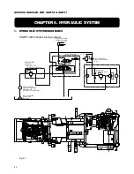
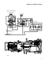
SERVICE MANUAL FOR SGR19 & SGR17
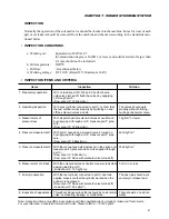
Troubles
Presumable causes
Countermeasures
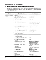
Abnormal vibration is
1. Hydraulic system
observed.
Trapped air
Bleed system of air.
2. Chassis
Worn joints
Replace with new ones.
Abnormal noises
1. Hydraulic system
(abnormal relief noise
a. A specific hydraulic apparatus
Consult with manufacturer of such
included)
generates noises.
apparatus.
b. Hydraulic pipes interfere
Eliminate interference.
with each other.
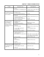
2. Directly connected valve or other
related valves
a. Dust trapped in steering relief valve
Disassemble, wash, re-assemble,
or overloadrelief valve, or
reset pre-setpressure, or replace
abnormally worn valves
defective valve assemblies with
new ones.
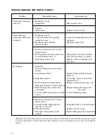
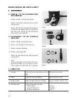
Oil leakage
1. Orbit-roll
– Worn or damaged oil seal of axle
(spool)
a. Contaminated fluid
Replace fluid and filter element
with new.
b. High back pressure
Lower back pressure lower than
specified level.
c. Rusted spool or sealing surfaces
Replace orbit-roll with a new one.
– Damaged O-rings of contact surfaces
e. Bitten O-rings when orbit-roll is
Replace damaged O-rings with
overhauled
new ones.
f. Too low tightening torque of end cap
Correct tightening torque.
screws
2. Directly connected valve or other
elated valves
a. Loosened bolts tightening valve
Re-tighten bolts to specified torque.
directly to orbit-roll
b. Damaged O-rings
Replace with new ones.
c. Damaged sealing surfaces and
Replace damaged parts or assemblies.
grooves
Although various trouble causes are listed above, almost all troubles reported in the market are caused
by dust trapped in the system. Therefore take sufficient care to avoid dust when servicing the hydraulic
system.
Содержание SCM49
Страница 1: ...S E R V I C E M A N U A L I S E K I L A W N M O W E R S LAWN MOWERS MOWER DECKS SCM48 SCM54 ...
Страница 7: ...7 CHAPTER 1 INTRODUCTION 3 EXTERIOR VIEW AND DIMENSIONS 1935 mm 1965 mm 1100 mm 1265 mm ...
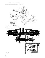
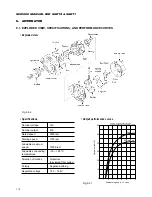
Страница 36: ...36 SERVICE MANUAL FOR SGR19 SGR17 Fig 3 55 III 3 CYLINDER BLOCK 1 EXPLODED VIEWS ...
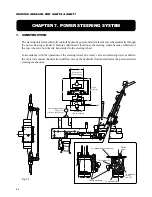
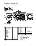
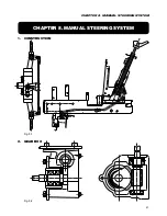
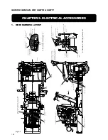
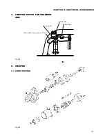
Страница 97: ...97 CHAPTER 8 MANUAL STEERING SYSTEM CHAPTER 8 MANUAL STEERING SYSTEM 1 CONSTRUCTION Fig 8 1 2 GEAR BOX Fig 8 2 ...