

16
SERVICE MANUAL FOR SGR19 & SGR17
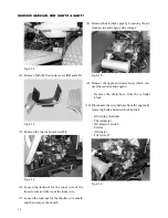
Note:
Keep on pushing the engine forward while lift-
ing it up to avoid damaging the radiator shroud
and cooling fan.
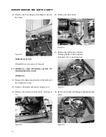
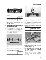
REINSTALLATION
Note:
Reassemble in reverse order of disassembly. But
check every part and replace defective ones.
(1) Install the engine on the frame.
– Install both insulators so that they are bent
slightly outwards.
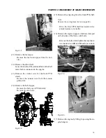
Note:
– The bolts which tighten the insulators on the
frame should be loosened in advance.
– Install both stoppers so that there is a clearance
of 1.5 to 4.5 mm on both sides in the engine
bracket.
– The engine should not be slanted either to the
right or to the left.
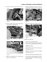
(2) Install the front PTO and related parts.
– Install the PTO pulley and shaft.
– Set the belt and tension pulley.
– Install the stopper and cover.
(3) Install the drive shaft.
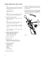
(4) Install fuel pipes.
– Install the pipes on the injection pump.
– Install the fuel return pipes on the nozzles.
(5) Connect wire harness.
– Glow plug terminals
– Thermometer
– Oil pressure switch
– Starter
– Alternator
– Fuel cut-off unit
(6) Install radiator hoses.
(7) Install the air intake pipe, throttle wire, tension
arm wire, etc., and then check that they have been
installed securely.
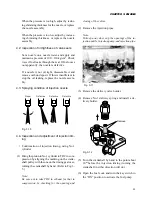
– The front PTO clutch control wire should be
connected with the tension spring through the
wire holder and the hole at the right-hand bot-
tom of the steering post.
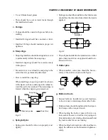
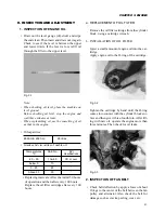
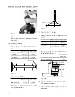
Fig. 2-21
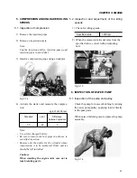
PTO
ON
0.2 to
0.3 mm
Содержание SCM49
Страница 1: ...S E R V I C E M A N U A L I S E K I L A W N M O W E R S LAWN MOWERS MOWER DECKS SCM48 SCM54 ...
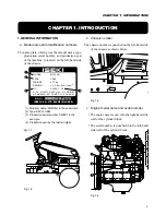
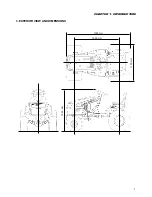
Страница 7: ...7 CHAPTER 1 INTRODUCTION 3 EXTERIOR VIEW AND DIMENSIONS 1935 mm 1965 mm 1100 mm 1265 mm ...
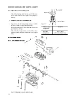
Страница 36: ...36 SERVICE MANUAL FOR SGR19 SGR17 Fig 3 55 III 3 CYLINDER BLOCK 1 EXPLODED VIEWS ...
Страница 97: ...97 CHAPTER 8 MANUAL STEERING SYSTEM CHAPTER 8 MANUAL STEERING SYSTEM 1 CONSTRUCTION Fig 8 1 2 GEAR BOX Fig 8 2 ...