23
CHAPTER 3. ENGINE
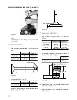
When the pressure is too high, adjust by reduc-
ing shimming thickness for the nozzle, or replace
the nozzle assembly.
When the pressure is too low, adjust by increas-
ing shimming thickness, or replace the nozzle
assembly.
4.2. Inspection of oil tightness of valve seats
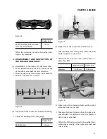
Set a nozzle on a nozzle tester, and apply and
maintain a pressure of 100 – 110 kg/cm
2
. Check
it see if fuel leaks through the seat. If fuel oozes
out apparently, the nozzle is defective.
If a nozzle is not oil tight, disassemble it and
remove carbon deposit. If this is insufficient to
stop the oil leaking, replace the nozzle assem-
bly.
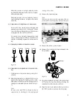
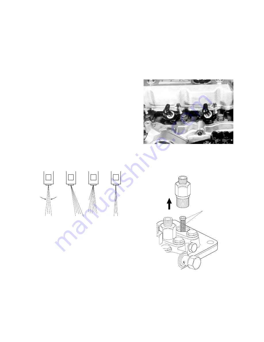
4.3. Spraying condition of injection nozzle
closing of the valves.
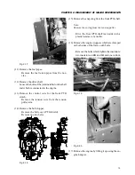
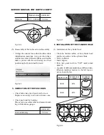
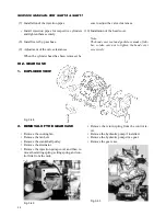
(2) Remove the injection pipes.
Note:
To keep away dust, cap the openings of the in-
jection nozzle, injection pump, and injection pipe.
Fig. 3-10
4.4. Inspection and adjustment of injection tim-
ing
• Confirmation of injection timing, using No.1
cylinder
(1) Bring the piston in No.1 cylinder to TDC in com-
pression by aligning the marking on the crank-
shaft pulley with the one on the timing gear case,
turning the crankshaft by hand. (Refer to Fig. 3-
5.)
Note:
Be sure not to take TDC in exhaust for that in
compression by checking for the opening and
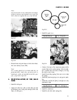
Fig. 3-11
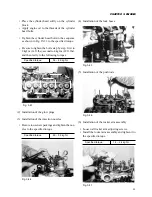
(3) Remove the delivery valve holder.
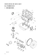
(4) Remove No.1 delivery spring and install a de-
livery holder.
Remove
Fig. 3-12
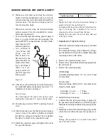
(5) Turn the crankshaft by hand to the point about
10
°
before the injection timing (turning the
crankshaft in either direction will do).
(6) Open the fuel cock and turn the key switch to
the “ON” position to activate the fuel pump.
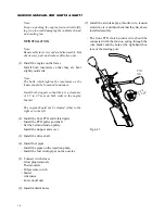
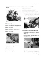
Proper
Defective
Defective
Defective
4
°
Содержание SCM49
Страница 1: ...S E R V I C E M A N U A L I S E K I L A W N M O W E R S LAWN MOWERS MOWER DECKS SCM48 SCM54 ...
Страница 7: ...7 CHAPTER 1 INTRODUCTION 3 EXTERIOR VIEW AND DIMENSIONS 1935 mm 1965 mm 1100 mm 1265 mm ...
Страница 36: ...36 SERVICE MANUAL FOR SGR19 SGR17 Fig 3 55 III 3 CYLINDER BLOCK 1 EXPLODED VIEWS ...
Страница 97: ...97 CHAPTER 8 MANUAL STEERING SYSTEM CHAPTER 8 MANUAL STEERING SYSTEM 1 CONSTRUCTION Fig 8 1 2 GEAR BOX Fig 8 2 ...

