

93
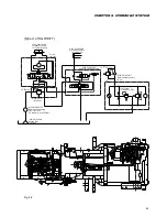
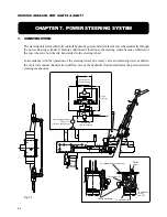
CHAPTER 7. POWER STEERING SYSTEM
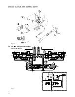
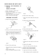
alternatively. Make the end of the spool/sleeve
assembly and the end of the G-rotor side of the
housing be flush. In this state, the assembly
should turn smoothly.
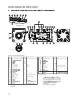
(12) Fit O-ring (22) into housing (2).
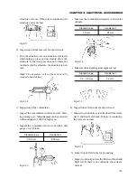
(13) Put spacer plate (24) on the housing and align
the bolt holes and oil holes in the housing and
spacer plate.
(14) Insert drive (21). Engage the yoke of the drive
with pin (8).
(15) Fit O-ring (22) to G-rotor (25), the O-ring groove
side of the G-rotor ring to the spacer plate, and
the counter sunk side of the G-rotor star and en-
gage the spline of the drive with that of the star.
Then align bolt holes and oil holes.
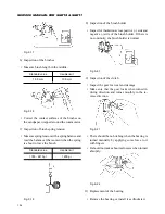
(16) Insert spacer (26) into the splined part in the G-
rotor star.
(17) Fit O-ring (28) to plate (27) and install the as-
sembly to the countersunk part in the G-rotor
star.
(18) Fit O-ring (22) to end cap (23) and put the as-
sembly on the G-rotor and align the bolt holes.
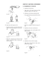
(19) Apply oil to the threads of cap screws (29) and
install the screws into end cap (28). The seven
screws should be tightened to 0.5 kgf·m first and
then tighten them further to 1.0 kgf·m. Set the
spool to the steering wheel and make sure that
the spool should turn smoothly.
With this, reassembly operation is completed.
Содержание SCM49
Страница 1: ...S E R V I C E M A N U A L I S E K I L A W N M O W E R S LAWN MOWERS MOWER DECKS SCM48 SCM54 ...
Страница 7: ...7 CHAPTER 1 INTRODUCTION 3 EXTERIOR VIEW AND DIMENSIONS 1935 mm 1965 mm 1100 mm 1265 mm ...
Страница 36: ...36 SERVICE MANUAL FOR SGR19 SGR17 Fig 3 55 III 3 CYLINDER BLOCK 1 EXPLODED VIEWS ...
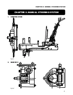
Страница 97: ...97 CHAPTER 8 MANUAL STEERING SYSTEM CHAPTER 8 MANUAL STEERING SYSTEM 1 CONSTRUCTION Fig 8 1 2 GEAR BOX Fig 8 2 ...