


43
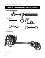
ISEKI LAWN MOWERS
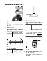
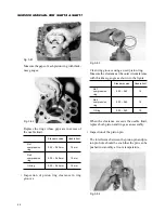
Clearance between journal and bearing:
Standard value
Usable limit
0.05 – 0.105 mm
0.12 mm
If the clearance exceeds the usable limit, replace
the camshaft with a new one.
Fig. 3-78
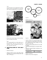
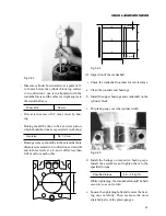
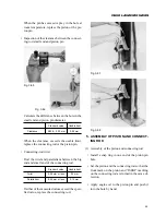
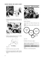
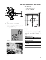
• Thrust play of the camshaft
Install the thrust plate and cam gear on the cam-
shaft. Push the thrust plate fully against the cam
gear and measure the clearance between the
thrust plate and journal with thickness gauges.
Standard value
Usable limit
0.05 – 0.174 mm
0.3 mm
Fig. 3-79
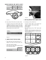
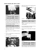
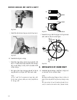
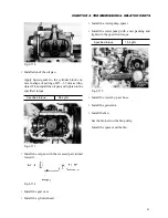
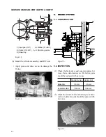
(5) Inspection of tappets
• Check the contact surface with the camshaft for
pitting, cracks, etc. Defective tappets should be
replaced with new ones.
Pitting
Cracking
Proper contact
Improper tappet contact
Fig. 3-80
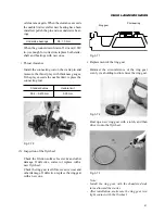
• Check the outer diameter for wear.
Standard value
Usable limit
20 mm
19.95 mm
Replace the tappets having diameters less than
the usable limit.
• Clearance of the tappets with the cylinder block
Measure the bore diameter of each tappet hole
in the cylinder block and the outer diameter of
each tappet. Then calculate the difference.
Replace the tappets which have clearances in
excess of the usable limit.
Standard value
Usable limit
0.02 – 0.062 mm
0.1 mm
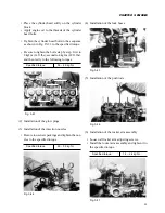
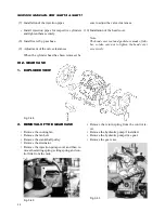
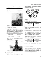
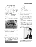
4. INSPECTION OF PISTONS AND CON-
NECTING RODS
• Check piston ring gaps.
Push a piston ring into the cylinder, using a pis-
ton as a pushing tool, to a point past the position
where the ring would be during operation i.e. to
the lower end of the cylinder wall.
If the clearance exceeds the usable limit, replace
the thrust plate.
Содержание SCM49
Страница 1: ...S E R V I C E M A N U A L I S E K I L A W N M O W E R S LAWN MOWERS MOWER DECKS SCM48 SCM54 ...
Страница 7: ...7 CHAPTER 1 INTRODUCTION 3 EXTERIOR VIEW AND DIMENSIONS 1935 mm 1965 mm 1100 mm 1265 mm ...
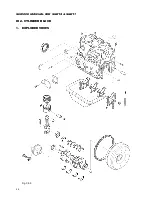
Страница 36: ...36 SERVICE MANUAL FOR SGR19 SGR17 Fig 3 55 III 3 CYLINDER BLOCK 1 EXPLODED VIEWS ...
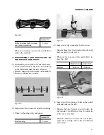
Страница 97: ...97 CHAPTER 8 MANUAL STEERING SYSTEM CHAPTER 8 MANUAL STEERING SYSTEM 1 CONSTRUCTION Fig 8 1 2 GEAR BOX Fig 8 2 ...