


64
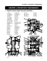
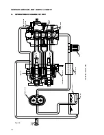
SERVICE MANUAL FOR SGR19 & SGR17
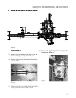
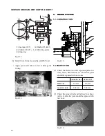
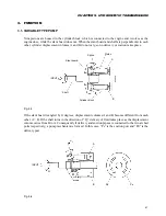
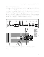
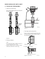
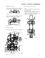
CHECK VALVE
The check valves are installed symmetrically in both sides across the charge passage “C.”
The check valve prevents the fluid from the high pressure passage “A” from flowing back into the
charge passage “C” and replenish the charge fluid in the passage “B.” But the fluid flows back through
the neutral orifice in accordance with the pressure applied to passage “C.”
The check valve in the high pressure side “A” closes and that in the low pressure side “B” is pushed
open by the charge pressure and the check valve end in the high pressure side.
A
C
C
C
B
Neutral orifices
Fig. 5-8
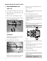
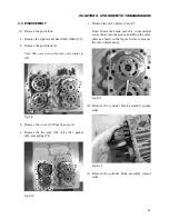
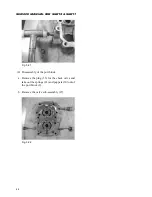
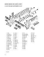
4.
DISASSEMBLY AND REASSEMBLY
This section describes the disassembly and reassembly procedures and precautions of the two-axle type
HST unit model HVFD-21A21-M.
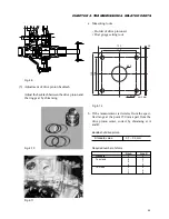
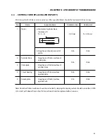
4.1. REQUIRED TOOLS
Ref. ....................................... Name ................................................................................................... Size and specified values
1 ................ Plastic hammer ................................................................................. Hammering light alloy parts: 0.3 kgf
2 ................ Screw driver (conventional) ............................................................. Nominal 150 mm
3 ................ Snap-ring pliers (for hole type) ........................................................ H-2, H-3
4 ................ Snap-ring pliers (for shaft type) ....................................................... S-1, S-3
5 ................ Hexagonal spanner ........................................................................... Face-to-face width::
5
mm
6
mm
8
mm
6 ................ Torque wrench .................................................................................. Specified torque:
51.0
N·m
49.0
N·m
36.8
N·m
29.4
N·m
17.5
N·m
7 ................ Hexagonal bits for torque wrench .................................................... Face-to-face width:
5
mm
6
mm
8
mm
8 ................ Socket for torque wrench ................................................................. Face-to-face width:
26
mm
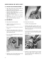
4.2. PRECAUTIONS FOR DISASSEMBLY
a. Clean the exterior of the casing completely first taking care to cover all ports to avoid the entry of dust.
b. Drain the case of oil.
c. Select a clean, dust-free place to work in to prevent dust affecting precision parts.
d. Handle disassembled parts carefully to avoid damage like dents, scratches, etc. by dropping or striking
them.
Содержание SCM49
Страница 1: ...S E R V I C E M A N U A L I S E K I L A W N M O W E R S LAWN MOWERS MOWER DECKS SCM48 SCM54 ...
Страница 7: ...7 CHAPTER 1 INTRODUCTION 3 EXTERIOR VIEW AND DIMENSIONS 1935 mm 1965 mm 1100 mm 1265 mm ...
Страница 36: ...36 SERVICE MANUAL FOR SGR19 SGR17 Fig 3 55 III 3 CYLINDER BLOCK 1 EXPLODED VIEWS ...
Страница 97: ...97 CHAPTER 8 MANUAL STEERING SYSTEM CHAPTER 8 MANUAL STEERING SYSTEM 1 CONSTRUCTION Fig 8 1 2 GEAR BOX Fig 8 2 ...