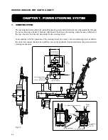


92
SERVICE MANUAL FOR SGR19 & SGR17
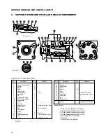
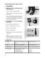
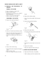
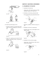
4.2. REASSEMBLY
Inspect all disassembled parts for contact sur-
faces for flaws and burr. The parts which have
such defects should be replaced with new ones
because such defects will cause oil leaks. All
metal parts should be washed in fresh solvent
and dried by blowing. Never wipe them with
cloth or paper because paper scrap or lint may
stick on them, which also may cause troubles.
Never try smoothing them with a file or coarse
sand paper.
Note: Principally we recommend the use of new
O-rings and seals when reassembling the mini-
orbit roll. They should be coated with a small
amount of fresh grease ahead of time.
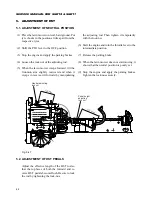
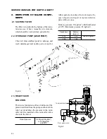
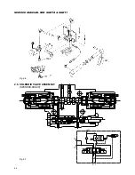
Reassembly of relief valve (only when a relief
valve is installed)
When reassembling a mini-orbit roll without a
relief valve, start reassembling at step 5.
(1) Hold the spring guide of poppet (17) with tweez-
ers and insert it through the flange of the hous-
ing as shown in section A-A. Make sure that the
poppet is installed properly.
(2) Insert spring (18) and damper collar (32).
(3) Fit O-ring (19) onto relief adjusting plug (20)
and screw in the plug into housing (2) as shown
in section A – A.
(4) Adjust the pre-set pressure of the steering relief
valve after the mini-orbit roll has been reassem-
bled. When the valve is required to be set to the
pre-disassembled pressure, re-set it to the same
depth as it is before disassembly at disassem-
bling step 18. The pressure shift by one turn of
relief adjusting plus is about 15 kgf·cm
2
.
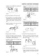
(5) Install ball (16) and retainer pin (15) in this or-
der into the tapped hole in housing (2) as shown
in section A – A. Then set retainer screw (13)
and tighten it to 1.3 kgf·m with a 3.0 m hexago-
nal set screw wrench.
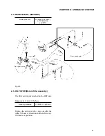
(6) Insert dust seal (13) from the end of housing (2)
with the flat surface turned downward.
(7) Installation of oil seal (12)
a. Install one bearing race (11) and sleeve (3) into
the bore of housing (2).
b. The space formed by the installed bearing race
and the housing provides a groove for oil seal
(12).
c. Push the sleeve inward manually from the G-
rotor side so that the centres of the sleeve and
the bearing race is almost aligned.
d. While keeping the sleeve and bearing race
aligned in centre, set oil seal (12) in the groove
from the flange side of the housing.
e. After having installed the oil seal, remove the
pre-installed sleeve and bearing race.
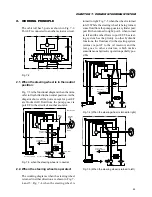
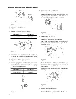
(8) Place the housing with the flange turned down-
ward and install bearing race (11), thrust needle
bearing (10), and bearing race (11) in this order.
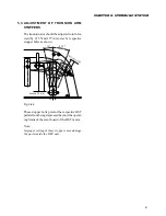
(9) Insert sleeve (3) onto spool (4) and align the
spring installation openings in the spool and
sleeve. Then first insert two flat springs (7) and
next insert all the centring springs to be installed
into the openings at the same time while two
halves of the centring springs are set as shown
in the drawing: the two halves should be faced
in opposite directions.
(10) After inserting the springs, fit spring retaining
ring (9) over the springs. Apply grease to the
clearance between the sleeve and retaining ring.
Insert pin (8) through the sleeve and spool. With
this operation, the spool/sleeve assembly is com-
pleted.
(11) Install the spool/sleeve assembly from the G-ro-
tor side.
Note: When inserting the spool/sleeve assembly,
take care not to allow it to slant and bite the
housing. Insert it with the pin kept level while
turning the assembly a little in both directions
Содержание SCM49
Страница 1: ...S E R V I C E M A N U A L I S E K I L A W N M O W E R S LAWN MOWERS MOWER DECKS SCM48 SCM54 ...
Страница 7: ...7 CHAPTER 1 INTRODUCTION 3 EXTERIOR VIEW AND DIMENSIONS 1935 mm 1965 mm 1100 mm 1265 mm ...
Страница 36: ...36 SERVICE MANUAL FOR SGR19 SGR17 Fig 3 55 III 3 CYLINDER BLOCK 1 EXPLODED VIEWS ...
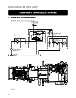
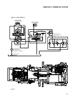
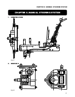
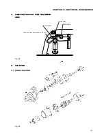
Страница 97: ...97 CHAPTER 8 MANUAL STEERING SYSTEM CHAPTER 8 MANUAL STEERING SYSTEM 1 CONSTRUCTION Fig 8 1 2 GEAR BOX Fig 8 2 ...