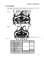

121
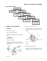
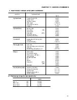
CHAPTER 10. MOWER DECK
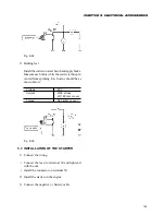
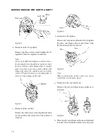
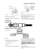
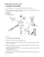
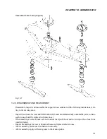
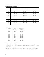
3.1.2. BACKLASH ADJUSTMENT
(1) Prepare the jig as show in the drawing to measure the backlash at R25 mm of the output shaft.
Adjusting shims (0.1, 0.2 mm)
Adjusting shims (0.1, 0.2 mm)
Lock this shaft
for backlash
measurement.
R25 mm
Fig. 10-3
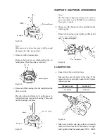
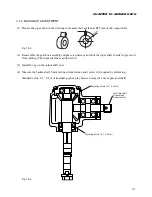
(2) Reassemble the gear box assembly and place it sideways and lock the input shaft in order to prevent it
from turning. (The input shaft has a splined end.)
(3) Install the jig on the output shaft end.
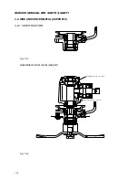
(4) Measure the backlash at 25-mm radius circumference and correct it if required by shimming.
Standard value: 0.3 – 0.5 mm (including spline play between respective bevel gear and shaft)
Fig. 10-4
Содержание SCM49
Страница 1: ...S E R V I C E M A N U A L I S E K I L A W N M O W E R S LAWN MOWERS MOWER DECKS SCM48 SCM54 ...
Страница 7: ...7 CHAPTER 1 INTRODUCTION 3 EXTERIOR VIEW AND DIMENSIONS 1935 mm 1965 mm 1100 mm 1265 mm ...
Страница 36: ...36 SERVICE MANUAL FOR SGR19 SGR17 Fig 3 55 III 3 CYLINDER BLOCK 1 EXPLODED VIEWS ...
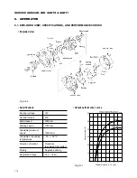
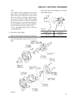
Страница 97: ...97 CHAPTER 8 MANUAL STEERING SYSTEM CHAPTER 8 MANUAL STEERING SYSTEM 1 CONSTRUCTION Fig 8 1 2 GEAR BOX Fig 8 2 ...