71
CHAPTER 5. HYDROSTATIC TRANSMISSION
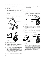
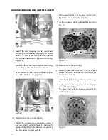
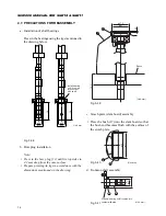
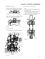
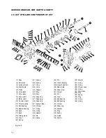
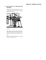
Fig. 5-26
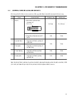
Tightening torqe
17.2
±
2 N·m
of screw (71)
* As for oil seal installation, refer to page 75.
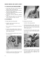
• Reassembly of the motor side shaft
a. Install the motor shaft assembly, which is com-
posed of the shaft (9), ball bearing (14), and snap-
ring (36), into the case (1) and retain the shaft
with the snap-ring (37).
* As for the details of the motor shaft assembly
refer to Fig. 5-37 and as for ball bearing instal-
lation to page 74.
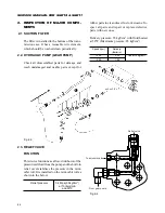
Fig. 5-27
Fig. 5-29
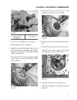
b. Install the two bushes (16) in the case (1).
c. Install the sliding piece (18) onto the trunnion
shaft (10).
b. Press the bore plug (11) into the case (1) and
install the snap-ring (37) on the outside.
Fig. 5-28
(3) Reassembly of the slant board and thrust bear-
ing
a. Install the thrust bearing (13) into the case (1).
Install the thrust bearing with the side bearing
no marking turned towards the pistons.
Содержание SCM49
Страница 1: ...S E R V I C E M A N U A L I S E K I L A W N M O W E R S LAWN MOWERS MOWER DECKS SCM48 SCM54 ...
Страница 7: ...7 CHAPTER 1 INTRODUCTION 3 EXTERIOR VIEW AND DIMENSIONS 1935 mm 1965 mm 1100 mm 1265 mm ...
Страница 36: ...36 SERVICE MANUAL FOR SGR19 SGR17 Fig 3 55 III 3 CYLINDER BLOCK 1 EXPLODED VIEWS ...
Страница 97: ...97 CHAPTER 8 MANUAL STEERING SYSTEM CHAPTER 8 MANUAL STEERING SYSTEM 1 CONSTRUCTION Fig 8 1 2 GEAR BOX Fig 8 2 ...


