

12
SERVICE MANUAL FOR SGR19 & SGR17
• Apply an adhesive (THREE BOND TB1104) to
parts through which there is any possibility of
oil leaks, such as stud bolts and tapped-through
parts.
• Each lock nut must be tightened securely.
• When tightening bolts and nuts, refer to the tight-
ening torque table.
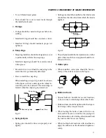
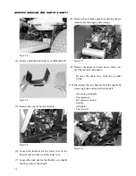
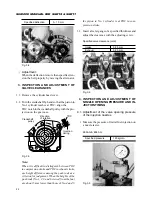
h. After installation, each grease fitting
should be filled with grease.
• When installing grease fittings of types B and
C, be sure to turn the fitting tips in a direction
that will provide easy access for a grease gun.
i. Other precautions
• Be sure not to damage any finished surfaces or
parts.
• Always refrain from forcing installation.
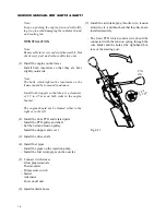
• Each lever knob should be installed coated with
an adhesive (SUPER THREE CEMENT
TB1702)
• Each contact surface should be coated with an
adhesive (THREE BOND TB1215) and tight-
ened evenly with bolts. Adhesive coated surfaces
should be installed within 30 minutes after ap-
plication of the adhesive.
The contact surfaces should be flawless and free
from foreign matter,, and especially from grease
before application of the adhesive.
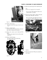
– Contact surfaces of the sleeve metal (support)
and front transmission case
– Contact surfaces of the hydraulic control le-
ver guide and cylinder case
• Precautions for applying adhesives
– The surface or the thread where an adhesive
is to be applied should be completely free of
chips and oil.
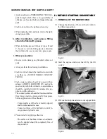
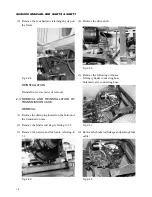
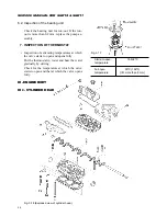
II. BEFORE STARTING DISASSEMBLY
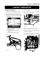
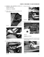
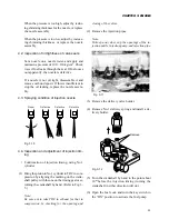
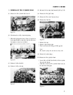
1. REMOVAL OF THE MOWER DESK
(1) Change the direction of the rear wheels when in
the lifted-up position.
Fig. 2-4
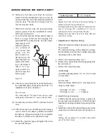
(2) Start the engine and lower the lift by the lift
switch.
Fig. 2-5
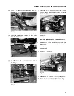
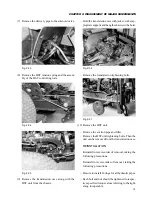
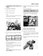
(3) Pull out the link pin and remove the support link.
Fig. 2-6
Содержание SCM49
Страница 1: ...S E R V I C E M A N U A L I S E K I L A W N M O W E R S LAWN MOWERS MOWER DECKS SCM48 SCM54 ...
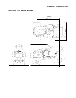
Страница 7: ...7 CHAPTER 1 INTRODUCTION 3 EXTERIOR VIEW AND DIMENSIONS 1935 mm 1965 mm 1100 mm 1265 mm ...
Страница 36: ...36 SERVICE MANUAL FOR SGR19 SGR17 Fig 3 55 III 3 CYLINDER BLOCK 1 EXPLODED VIEWS ...
Страница 97: ...97 CHAPTER 8 MANUAL STEERING SYSTEM CHAPTER 8 MANUAL STEERING SYSTEM 1 CONSTRUCTION Fig 8 1 2 GEAR BOX Fig 8 2 ...