


33
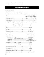
CHAPTER 3. ENGINE
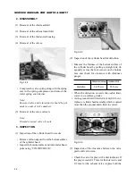
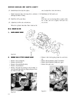
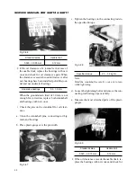
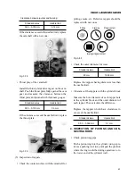
(4) Installation of the leak hoses.
Fig. 3-45
(5) Installation of the push rods
Fig. 3-46
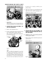
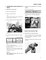
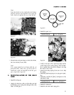
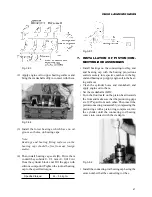
(6) Installation of the rocker arm assembly
• Loosen all rocker arm adjusting screws.
• Install the rocker arm assembly and tighten it to
the specified torque.
Specified torque
1.4 – 2.4 kgf·m
Fig. 3-47
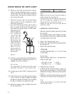
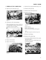
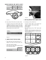
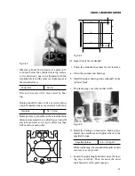
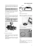
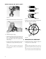
• Place the cylinder head softly on the cylinder
block.
• Apply engine oil to the threads of the cylinder
head bolts.
• Tighten the cylinder head bolts in the sequence
as shown in Fig. IV-31 to the specified torque.
• Be sure to tighten the bolts step by step: first to
2 kgf·m (14 ft·lbs), second to 4 kgf·m (29 ft·lbs),
and then lastly to the following torques.
Specified torque
5.5 – 6.0 kgf·m
1
2
3
4
5
6
7
8
9
10
11
12
13
14
Fig. 3-43
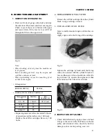
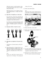
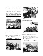
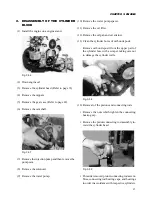
(2) Installation of the glow plugs
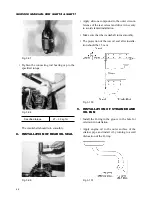
(3) Installation of the injection nozzles
• Be sure to use new packings and tighten the noz-
zles to the specified torque.
Specified torque
4.0 – 5.5 kgf·m
Fig. 3-44
Содержание SCM49
Страница 1: ...S E R V I C E M A N U A L I S E K I L A W N M O W E R S LAWN MOWERS MOWER DECKS SCM48 SCM54 ...
Страница 7: ...7 CHAPTER 1 INTRODUCTION 3 EXTERIOR VIEW AND DIMENSIONS 1935 mm 1965 mm 1100 mm 1265 mm ...
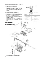
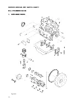
Страница 36: ...36 SERVICE MANUAL FOR SGR19 SGR17 Fig 3 55 III 3 CYLINDER BLOCK 1 EXPLODED VIEWS ...
Страница 97: ...97 CHAPTER 8 MANUAL STEERING SYSTEM CHAPTER 8 MANUAL STEERING SYSTEM 1 CONSTRUCTION Fig 8 1 2 GEAR BOX Fig 8 2 ...