


47
ISEKI LAWN MOWERS
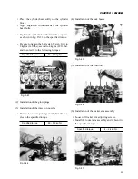
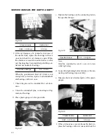
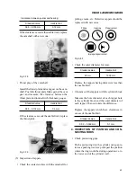
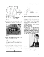
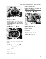
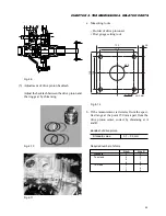
Fig. 3-93
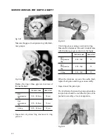
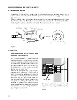
(2) Apply engine oil to upper bearing surfaces and
bring the crankshaft softly in contact with them.
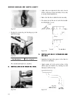
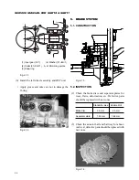
Fig. 3-94
(3) Install the lower bearings, which have no oil
grooves or holes, on bearing caps.
Note:
Bearings and bearing fitting surfaces on the
bearing caps should be free from any foreign
matter.
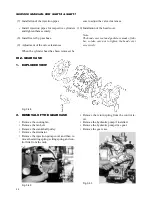
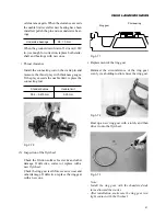
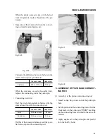
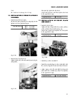
(4) Then install bearing cap seals (B). Drive them
in until they subside 0 – 0.3 mm (0 – 0.012 in.)
from the cylinder block end. Fill the gaps with
silicone compound. Tighten the journal bearing
cap to the specified torque.
Specified torque:
4.5 – 5.5 kgf·m
Fig. 3-95
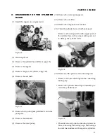
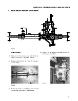
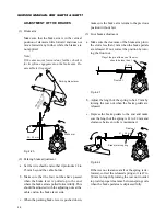
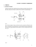
7.
INSTALLATION OF PISTON/CON-
NECTING-ROD ASSEMBLIES
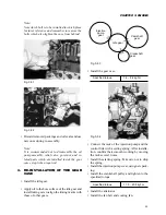
• Install bearings on the connecting-rod big end
and bearing cap with the bearing projections
seated securely in respective notches in the big
end and bearing cap. Apply engine oil to the bear-
ing surfaces.
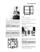
• Clean the cylinder bores and crankshaft, and
apply engine oil to them.
• Set the crankshaft at BDC.
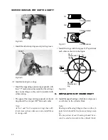
• Turn the front mark on the piston head towards
the front and make sure that the piston ring gaps
are 120
°
apart from each other. Then insert the
piston/connecting rod assembly, compressing the
piston rings with a piston ring compressor, into
the cylinder until the connecting rod bearing
comes into contact with the crankpin.
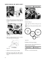
Fig. 3-96
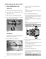
• Install the connecting-rod bearing cap having the
same number that the connecting rod has.
Содержание SCM49
Страница 1: ...S E R V I C E M A N U A L I S E K I L A W N M O W E R S LAWN MOWERS MOWER DECKS SCM48 SCM54 ...
Страница 7: ...7 CHAPTER 1 INTRODUCTION 3 EXTERIOR VIEW AND DIMENSIONS 1935 mm 1965 mm 1100 mm 1265 mm ...
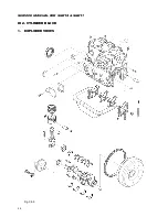
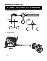
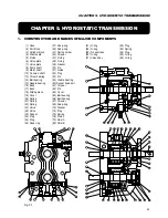
Страница 36: ...36 SERVICE MANUAL FOR SGR19 SGR17 Fig 3 55 III 3 CYLINDER BLOCK 1 EXPLODED VIEWS ...
Страница 97: ...97 CHAPTER 8 MANUAL STEERING SYSTEM CHAPTER 8 MANUAL STEERING SYSTEM 1 CONSTRUCTION Fig 8 1 2 GEAR BOX Fig 8 2 ...