

112
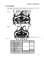
SERVICE MANUAL FOR SGR19 & SGR17
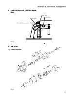
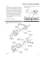
Fig. 9-40
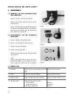
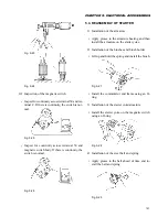
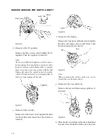
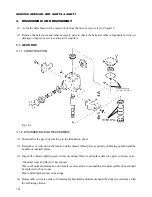
d. Removal of the IC regulator
Remove the three screws which tighten the IC
regulator. Then the regulator is removed.
Note:
As screws of different length are used for respec-
tive terminals, they should be set aside in order
for later reference after disassembly. A wrongly
used screw may come into contact with the end
frame and cause the regulator out of control,
which will lead to battery overcharging and re-
sult in serious damage in the end.
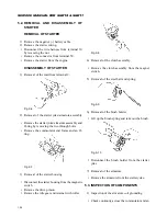
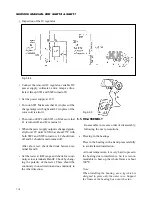
Fig. 9-41
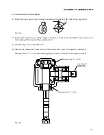
e. Removal of the rectifier
Remove the four screws which tighten the leads
for the rectifier and stator. Then the rectifier is
removed.
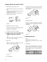
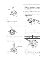
Fig. 9-42
f. Removal of the brushes
Remove the four nuts and bushes which tighten
the drive end frame and rear end frame. Then
the brush assembly is removed.
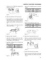
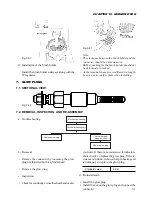
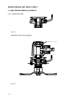
Fig. 9-43
Note:
When removing the bushes, take care not to
stretch the wire from the stator.
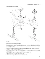
g. Removal of the rear end frame
Remove the rear end frame using a puller as il-
lustrated.
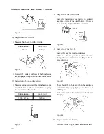
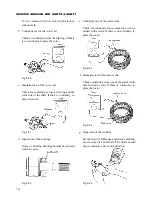
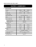
Fig. 9-44
h. Place the drive end frame on blocks as illustrated
to make it level and push out the rotor on a press.
Содержание SCM49
Страница 1: ...S E R V I C E M A N U A L I S E K I L A W N M O W E R S LAWN MOWERS MOWER DECKS SCM48 SCM54 ...
Страница 7: ...7 CHAPTER 1 INTRODUCTION 3 EXTERIOR VIEW AND DIMENSIONS 1935 mm 1965 mm 1100 mm 1265 mm ...
Страница 36: ...36 SERVICE MANUAL FOR SGR19 SGR17 Fig 3 55 III 3 CYLINDER BLOCK 1 EXPLODED VIEWS ...
Страница 97: ...97 CHAPTER 8 MANUAL STEERING SYSTEM CHAPTER 8 MANUAL STEERING SYSTEM 1 CONSTRUCTION Fig 8 1 2 GEAR BOX Fig 8 2 ...