


75
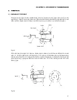
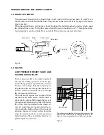
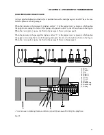
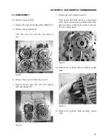
CHAPTER 5. HYDROSTATIC TRANSMISSION
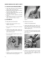
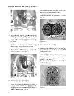
e. Installation of oil seals
• Press the oil seal (61) into the cover until the oil
seal end becomes flush with the cover surface.
ø35
ø20
19
61
(Unit: mm)
Fig. 5-42
• Press in the oil seal (67) until the oil seal end
sinks to 12.5 mm below the case surface.
1
67
68
ø30
ø17
12.5
(Unit: mm)
Fig. 5-43
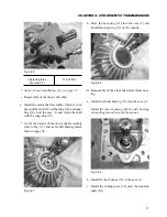
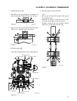
f, Port block assembly
As for the pressed-in parts, refer to paragraph g.
29.4N·m(3.0kgf·m)
29.4N·m(3.0kgf·m)
38.6N·m(3.75kgf·m)
51.0N·m(5.2kgf·m)
51.0N·m(5.2kgf·m)
29.4N·m(3.0kgf·m)
29.4N·m(3.0kgf·m)
47
21
21
48
48
27
33
30
30
48
47
48
34
34
33
34
34
50
50
Caulking point
4 mm
(Unit: mm)
Fig. 5-44
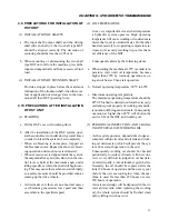
g. Pressed-in parts in the port block
Note:
• The oil seal (42) should be installed with the dust
lip turned outward.
• Install the bearing (15) until the end protrudes
by 2.5 mm beyond the port block surface.
• Prepare pressing-in jigs in accordance with the
dimensions mentioned on the drawing.
15
15
42
42
38
38
ø20
ø30
ø29
ø22
ø20
ø30
ø29
ø22
3
2.5
3
2.5
(Unit: mm)
Fig. 5-45
Содержание SCM49
Страница 1: ...S E R V I C E M A N U A L I S E K I L A W N M O W E R S LAWN MOWERS MOWER DECKS SCM48 SCM54 ...
Страница 7: ...7 CHAPTER 1 INTRODUCTION 3 EXTERIOR VIEW AND DIMENSIONS 1935 mm 1965 mm 1100 mm 1265 mm ...
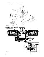
Страница 36: ...36 SERVICE MANUAL FOR SGR19 SGR17 Fig 3 55 III 3 CYLINDER BLOCK 1 EXPLODED VIEWS ...
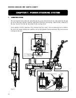
Страница 97: ...97 CHAPTER 8 MANUAL STEERING SYSTEM CHAPTER 8 MANUAL STEERING SYSTEM 1 CONSTRUCTION Fig 8 1 2 GEAR BOX Fig 8 2 ...