45
ISEKI LAWN MOWERS
When the pin has excessive play in the hole at
room temperature, replace the piston or the pis-
ton pin.
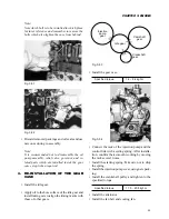
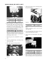
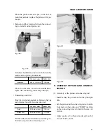
• Inspection of the clearance between the connect-
ing-rod small end and piston pin
Fig. 3-85
Fig. 3-86
Calculate the difference between the bore in the
small end and piston pin diameter.
Standard value
Usable limit
Clearance
0.008 – 0.02 mm
0.05 mm
When the clearance exceeds the usable limit,
replace the connecting rod or the piston pin.
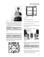
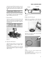
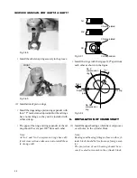
• Connecting-rod twist
Find the twist and parallelism between the big
end and small end of the connecting rod.
Standard value
Usable limit
Twist
0.05 mm or less
0.2 mm
Parallelism
0.05 mm or less
0.15 mm
If either of the measured values exceed the speci-
fied value, replace the connecting rod.
Fig. 3-87
Fig. 3-88
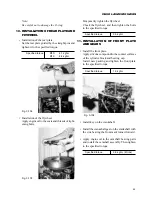
5. ASSEMBLY OF PISTON AND CONNECT-
ING ROD
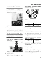
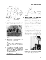
(1) Assembly of the piston and connecting rod
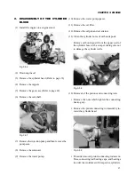
• Install a snap ring in one end of the piston pin
hole.
• Set the piston and the connecting rod so that the
front mark on the piston and “ISEKI” marking
on the connecting rod are turned in the same di-
rection.
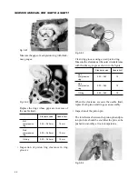
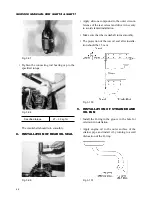
• Apply engine oil to the piston pin and push it
into the hole by hand.
Содержание SCM49
Страница 1: ...S E R V I C E M A N U A L I S E K I L A W N M O W E R S LAWN MOWERS MOWER DECKS SCM48 SCM54 ...
Страница 7: ...7 CHAPTER 1 INTRODUCTION 3 EXTERIOR VIEW AND DIMENSIONS 1935 mm 1965 mm 1100 mm 1265 mm ...
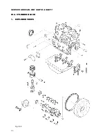
Страница 36: ...36 SERVICE MANUAL FOR SGR19 SGR17 Fig 3 55 III 3 CYLINDER BLOCK 1 EXPLODED VIEWS ...
Страница 97: ...97 CHAPTER 8 MANUAL STEERING SYSTEM CHAPTER 8 MANUAL STEERING SYSTEM 1 CONSTRUCTION Fig 8 1 2 GEAR BOX Fig 8 2 ...

