
116
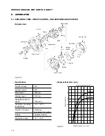
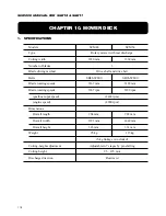
SERVICE MANUAL FOR SGR19 & SGR17
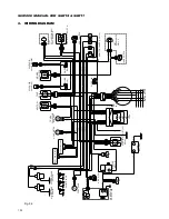
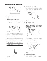
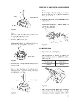
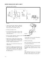
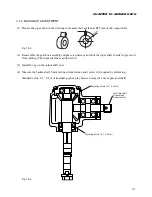
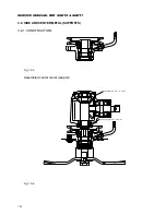
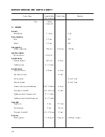
j. Inspection of the IC regulator
Fig. 9-59
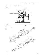
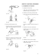
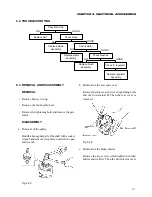
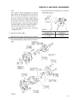
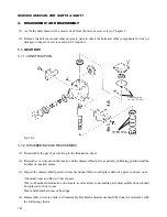
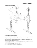
6.5. RE-ASSEMBLY
Re-assemble in reverse order of disassembly,
following the next precautions.
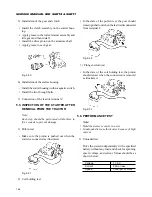
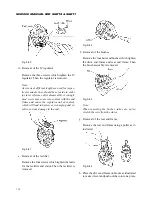
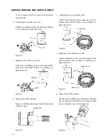
a. Pressing in the bearings
Press in the bearing with a hand press carefully
to avoid slanted installation.
At room temperature, it is very hard to press in
the bearing due to interference. So it is recom-
mendable to heat up the whole frame at about
100
°
C.
Note:
When installing the bearing, use a jig which is
designed to press only the outer race. Support
the frame at the bearing box not at the stay.
Fig. 9-58
• Connect the removed IC regulator, variable DC
power supply, voltmeter, and a lamp as illus-
trated. (Keep SW1 and SW2 turned off.)
• Set the power supply at 12V.
• Turn on SW1. Make sure that L1 (in place of the
charge lamp) is lit bright and L2 (in place of the
rotor coil) is also lit.
• Then turn on SW2 with SW1 on. Make sure that
L1 is turned off and L2 remains lit.
• When the power supply output is changed gradu-
ally from 12V until 14.5
±
0.6 at about 25
°
C with
both SW1 and SW2 turned on, L2 should turn
off and L1 should remain turned off.
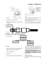
After above test, check the diode between ter-
minal B and F.
• Set the tester at K
Ω
range and check for conti-
nuity across terminals B and F. Check by chang-
ing the polarity of the tester. There should be
continuity in one direction and no continuity in
the other direction.
Содержание SCM49
Страница 1: ...S E R V I C E M A N U A L I S E K I L A W N M O W E R S LAWN MOWERS MOWER DECKS SCM48 SCM54 ...
Страница 7: ...7 CHAPTER 1 INTRODUCTION 3 EXTERIOR VIEW AND DIMENSIONS 1935 mm 1965 mm 1100 mm 1265 mm ...
Страница 36: ...36 SERVICE MANUAL FOR SGR19 SGR17 Fig 3 55 III 3 CYLINDER BLOCK 1 EXPLODED VIEWS ...
Страница 97: ...97 CHAPTER 8 MANUAL STEERING SYSTEM CHAPTER 8 MANUAL STEERING SYSTEM 1 CONSTRUCTION Fig 8 1 2 GEAR BOX Fig 8 2 ...