

13
CHAPTER 2. DISASSEMBLY OF MAJOR COMPONENTS
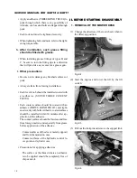
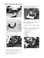
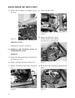
(4) Remove the fixed bolt and the stopper brackets.
Fig. 2-7
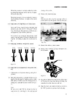
(5) Disconnect the universal joint of the drive shaft
from the front mower.
Fig. 2-8
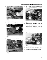
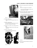
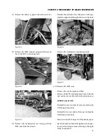
(6) Move the mower deck rearward to detach it from
the linkage.
Fig. 2-9
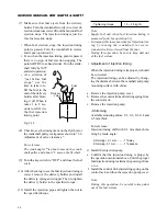
(7) Start the engine and lift up the linkage. Then
remove the mower deck sideways from the
mower engine.
Fig. 2-10
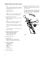
2. REMOVAL AND REINSTALLATION OF
MAJOR FUNCTIONAL COMPONENTS
2.1. REMOVAL AND REINSTALLATION OF
ENGINE
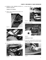
REMOVAL
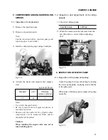
(1) Open the rear fender.
Fig. 2-11
(2) Disconnect the negative (-) post of the battery.
(3) Drain engine coolant through the drain plug.
Содержание SCM49
Страница 1: ...S E R V I C E M A N U A L I S E K I L A W N M O W E R S LAWN MOWERS MOWER DECKS SCM48 SCM54 ...
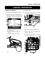
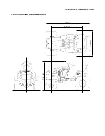
Страница 7: ...7 CHAPTER 1 INTRODUCTION 3 EXTERIOR VIEW AND DIMENSIONS 1935 mm 1965 mm 1100 mm 1265 mm ...
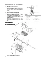
Страница 36: ...36 SERVICE MANUAL FOR SGR19 SGR17 Fig 3 55 III 3 CYLINDER BLOCK 1 EXPLODED VIEWS ...
Страница 97: ...97 CHAPTER 8 MANUAL STEERING SYSTEM CHAPTER 8 MANUAL STEERING SYSTEM 1 CONSTRUCTION Fig 8 1 2 GEAR BOX Fig 8 2 ...