


29
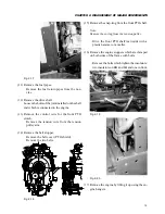
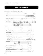
CHAPTER 3. ENGINE
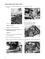
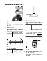
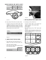
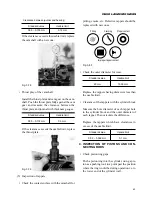
Specified bore
7 mm
Fig. 3-29
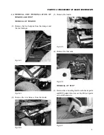
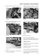
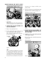
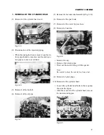
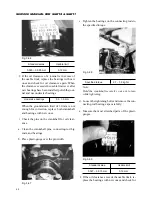
(5) Inspection and correction of valve seats.
• Check for valve contacting width and depres-
sion.
When the contact width is wider than specified,
correct with a 75
°
valve seat cutter. When the
valve depression is more than specified, replace
the cylinder head assembly.
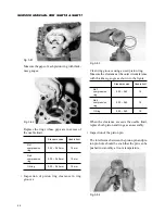
Standard value
Usable limit
Contact width
1.3 – 1.6 mm
2.0 mm
Valve depression
0.7 mm
1.4 mm
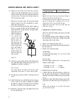
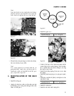
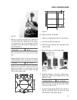
Valve guide
Cylinder head
7 mm
Contact
width
Subsidence
Fig. 3-30
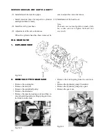
• Apply polishing compound to the valve seat sur-
face and lap with the valve while tapping the
valve to secure sufficiently contact with the
whole circumference.
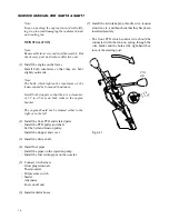
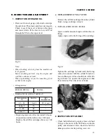
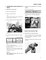
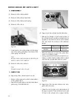
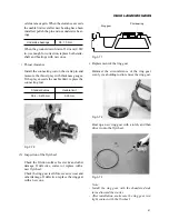
valve and valve guide as an assembly. Measure
the play at a point 10 mm apart above the valve
oil seal when the valve lift is 0 mm.
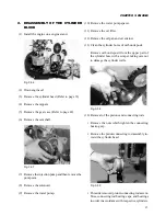
Fig. 3-27
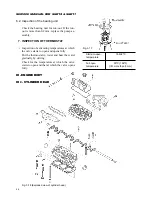
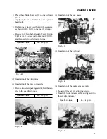
(4) Replacement of the valve guide.
• Drive out the valve guide upwards from the cyl-
inder head bottom.
• Press in a new valve guide from the cylinder head
top, taking care not to damage the guide.
Fig. 3-28
Note:
Apply oil to the new valve guide ahead of time.
• Press in so that the distance from the cylinder
head top to the valve guide end becomes 7 mm.
• After installation, correct the bore diameter of
the valve guide to the specified value by reaming.
Содержание SCM49
Страница 1: ...S E R V I C E M A N U A L I S E K I L A W N M O W E R S LAWN MOWERS MOWER DECKS SCM48 SCM54 ...
Страница 7: ...7 CHAPTER 1 INTRODUCTION 3 EXTERIOR VIEW AND DIMENSIONS 1935 mm 1965 mm 1100 mm 1265 mm ...
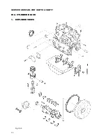
Страница 36: ...36 SERVICE MANUAL FOR SGR19 SGR17 Fig 3 55 III 3 CYLINDER BLOCK 1 EXPLODED VIEWS ...
Страница 97: ...97 CHAPTER 8 MANUAL STEERING SYSTEM CHAPTER 8 MANUAL STEERING SYSTEM 1 CONSTRUCTION Fig 8 1 2 GEAR BOX Fig 8 2 ...