37
CHAPTER 3. ENGINE
2.
DISASSEMBLY OF THE CYLINDER
BLOCK
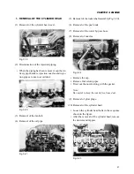
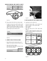
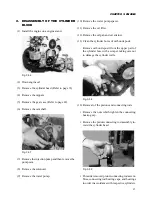
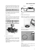
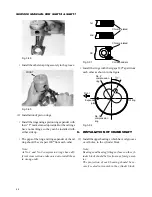
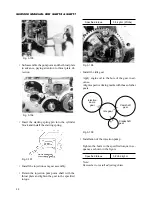
(1) Install the engine on a engine stand.
Fig. 3-56
(2) Drain engine oil.
(3) Remove the cylinder head (Refer to page 33).
(4) Remove the tappets.
(5) Remove the gear case (Refer to page 42).
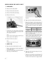
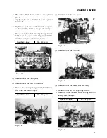
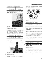
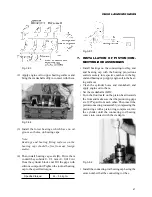
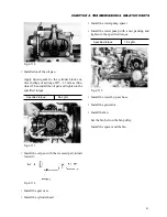
(6) Remove the camshaft.
Fig. 3-57
(7) Remove the injection pump and then remove the
pump cam.
(8) Remove the solenoid.
(9) Remove the water pump.
(10) Remove the water pump spacer.
(11) Remove the oil filter.
(12) Remove the oil pan and oil strainer.
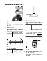
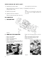
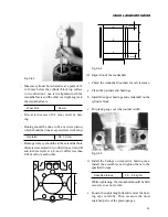
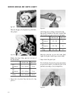
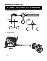
(13) Clean the cylinder bores of carbon deposit.
Remove carbon deposit from the upper part of
the cylinder bore with a scraper, taking care not
to damage the cylinder walls.
Fig. 3-58
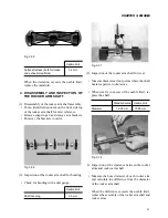
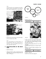
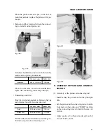
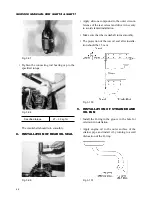
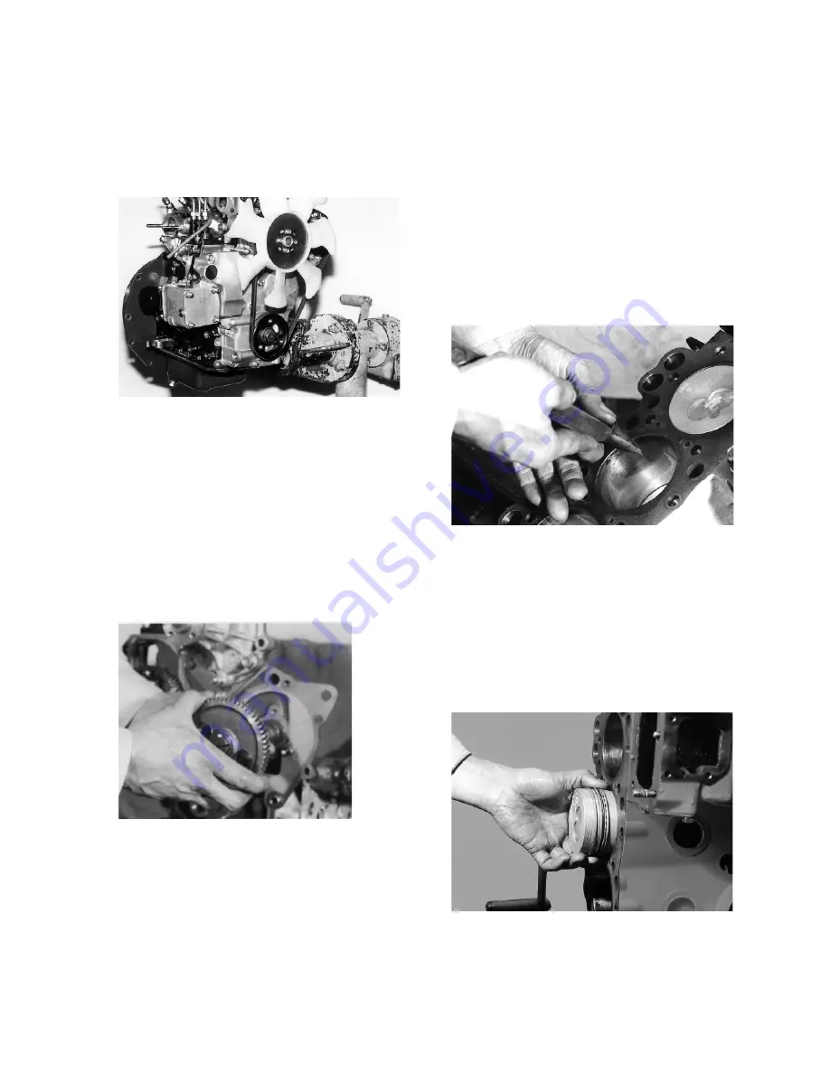
(14) Removal of the pistons and connecting rods.
• Remove the nuts which tighten the connecting
bearing cap.
• Remove the piston/connecting rod assembly to-
ward the cylinder head.
Fig. 3-59
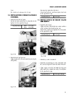
• Put aside removed piston/connecting rod assem-
blies, connecting rod bearing caps, and bearings
in order in accordance with respective cylinders.
Содержание SCM49
Страница 1: ...S E R V I C E M A N U A L I S E K I L A W N M O W E R S LAWN MOWERS MOWER DECKS SCM48 SCM54 ...
Страница 7: ...7 CHAPTER 1 INTRODUCTION 3 EXTERIOR VIEW AND DIMENSIONS 1935 mm 1965 mm 1100 mm 1265 mm ...
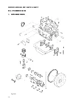
Страница 36: ...36 SERVICE MANUAL FOR SGR19 SGR17 Fig 3 55 III 3 CYLINDER BLOCK 1 EXPLODED VIEWS ...
Страница 97: ...97 CHAPTER 8 MANUAL STEERING SYSTEM CHAPTER 8 MANUAL STEERING SYSTEM 1 CONSTRUCTION Fig 8 1 2 GEAR BOX Fig 8 2 ...

