

91
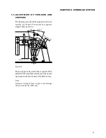
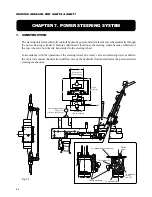
CHAPTER 7. POWER STEERING SYSTEM
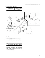
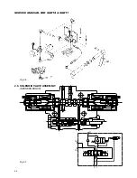
4.
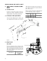
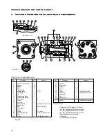
DISASSEMBLY & REASSEMBLY
Disassemble or reassemble the mini-orbit roll re-
ferring to the parts list and the drawing in Fig. 7-
6.
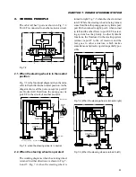
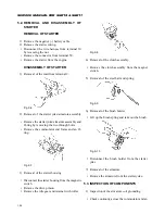
4.1. DISASSEMBLY
A clean place is essential for this operation. Be-
fore disconnecting the piping, clean the body of
the mini-orbit roll. Clean all dust accumulated
in the joints on the circumference with a wire
brush.
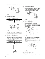
(1) Hold the component in the vise with the end cap
faced upward. Hold it lightly around the mount-
ing flange via copper plates to refrain from dam-
aging the housing.
(2) Remove seven cap screws (29).
(3) Remove end cap (23).
(4) Detach O-ring (22) from end cap (23).
(5) Remove plate (27) and O-ring (28) from the star
rotor of G-rotor (25) and extract spacer (26).
Note: The spacer is not installed in the mini-or-
bit rolls of 31 cm
3
/rev and 51 cm
3
/rev.
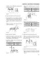
(6) Detach G-rotor (25) taking care not to allow the
star to fall from the outer ring of the G-rotor.
(7) Detach O-ring (22) from G-rotor (25).
(8) Remove drive (21).
(9) Remove spacer plate (24).
(10) Detach O-ring (22) from housing (2).
(11) Remove housing (2) from the vise and place the
housing level axially on cloth so that the finished
surfaces are not damaged.
After making pin (8) level by turning spool (4)
and sleeve (3), extract the spool/sleeve assem-
bly from the opposite side of the flange of hous-
ing (2) by pushing the spline of spool (4) .
Note: The spool/sleeve assembly is composed of
sleeve (3), spool (4), pin (8), centring spring (6),
thrust spring (7), and spring retaining ring (9).
When extracting the assembly from housing (2),
take care not to allow the sleeve to bite the bore
wall of the housing.
(12) Extract spring retaining ring (9) and pin (8) from
the spool/sleeve assembly.
(13) Push spool (4) a little forward from sleeve (4)
and disengage centring springs (6) and flat
springs (4) carefully by hand.
(14) Extract spool (4) from sleeve (3) by turning the
spool slowly.
Note: Do not remove retaining ring (9) from
spool (4).
(15) Detach two bearing races (11), thrust needle bear-
ing (10), and oil seal (12) from housing (2).
(16) Pry off dust seal (13) from the flange of housing
(2), taking care not to damage the housing.
(17) Take out retainer pin (15) and ball (16) by re-
moving retainer screw (14) from the tapped hole
shown by section A – A of the G-rotor side end
of housing (2).
Disassembly of relief valve (only when a relief
valve is installed)
(18) Place housing (2) with the flange face turned
upward, remove relief adjusting plug (20) and
O-ring (19).
Note: It is recommended to measure the depth
from the flange end to relief adjusting plug (2)
before disassembly for the convenience reassem-
bly.
(19) Detach dumper collar (32) and spring (18).
(20) Take out poppet (17) from housing (2) using
tweezers.
Содержание SCM49
Страница 1: ...S E R V I C E M A N U A L I S E K I L A W N M O W E R S LAWN MOWERS MOWER DECKS SCM48 SCM54 ...
Страница 7: ...7 CHAPTER 1 INTRODUCTION 3 EXTERIOR VIEW AND DIMENSIONS 1935 mm 1965 mm 1100 mm 1265 mm ...
Страница 36: ...36 SERVICE MANUAL FOR SGR19 SGR17 Fig 3 55 III 3 CYLINDER BLOCK 1 EXPLODED VIEWS ...
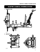
Страница 97: ...97 CHAPTER 8 MANUAL STEERING SYSTEM CHAPTER 8 MANUAL STEERING SYSTEM 1 CONSTRUCTION Fig 8 1 2 GEAR BOX Fig 8 2 ...