


70
SERVICE MANUAL FOR SGR19 & SGR17
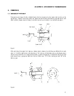
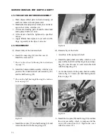
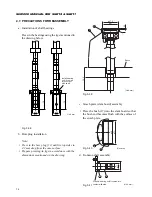
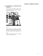
4.5. PRECAUTION BEFORE REASSEMBLY
a. Wash disassembled parts in fresh cleansing oil
and blow them with compressed air.
b. Handle the cleaned parts carefully to avoid dam-
age such as dents, scratches, etc.
c. All removed sealing parts should be discarded
and replaced with new ones.
d. All fasteners should be tightened to specified
values.
e. Apply lithium-based grease to oil seals and O-
rings: especially to the lips of oil seals.
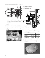
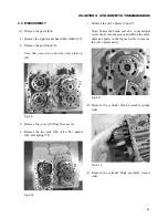
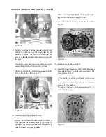
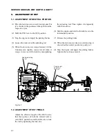
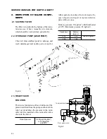
4.6. REASSEMBLY
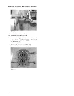
(1) Reassembly of the trunnion shaft
a. Install the snap-ring (38) into the case (1).
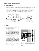
Install the oil seal (67).
* Press in the oil seal following the instructions
on page 75.
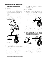
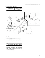
b. Install the trunnion shaft assembly, which is com-
posed of the trunnion shaft sub-assembly (65)
and the ball bearing (65).
* Press in the ball bearingfollowing the instruc-
tions on page 74.
Fig. 5-23
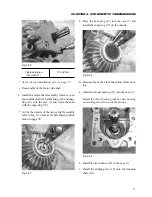
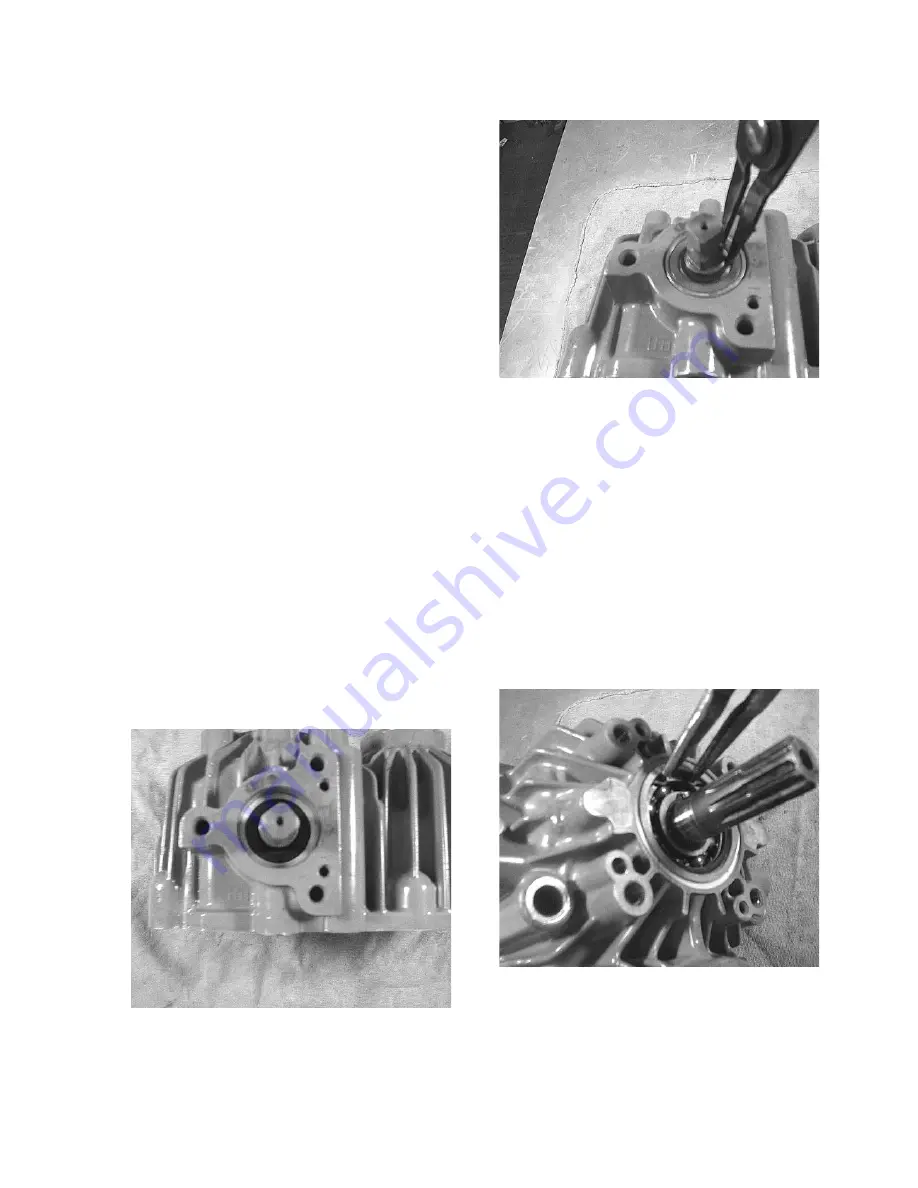
c. Install the washer (72) and ball bearing (66) and
retain the shaft with the snap-ring (69).
Fig. 5-24
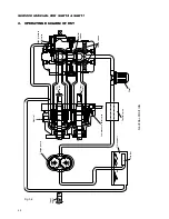
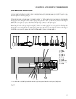
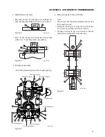
(2) Reassembly of the shafts
• Assembly of the pump-side shaft
a. Install the pump shaft assembly, which is com-
posed of the shaft (8), ball bearing (14), and snap-
ring (36), into the case (1) and retain the shaft
with the snap-ring (37).
* As for the details of the pump shaft assembly
refer to Fig. 5-37 and as for ball bearing instal-
lation to page 74.
Fig. 5-25
b. Install the two pins (50) and O-ring (82) and then
the cover assembly, which is composed of the
cover (19) and oil seal (61). Tighten the cover
with the screws (71).
Содержание SCM49
Страница 1: ...S E R V I C E M A N U A L I S E K I L A W N M O W E R S LAWN MOWERS MOWER DECKS SCM48 SCM54 ...
Страница 7: ...7 CHAPTER 1 INTRODUCTION 3 EXTERIOR VIEW AND DIMENSIONS 1935 mm 1965 mm 1100 mm 1265 mm ...
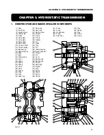
Страница 36: ...36 SERVICE MANUAL FOR SGR19 SGR17 Fig 3 55 III 3 CYLINDER BLOCK 1 EXPLODED VIEWS ...
Страница 97: ...97 CHAPTER 8 MANUAL STEERING SYSTEM CHAPTER 8 MANUAL STEERING SYSTEM 1 CONSTRUCTION Fig 8 1 2 GEAR BOX Fig 8 2 ...