

108
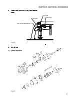
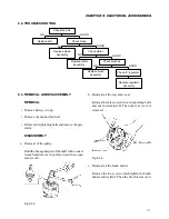
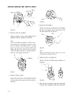
SERVICE MANUAL FOR SGR19 & SGR17
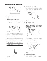
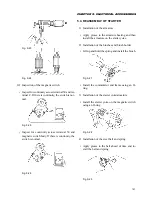
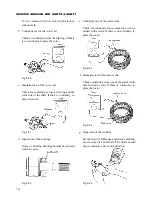
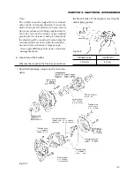
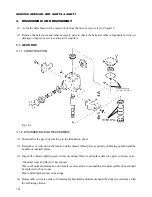
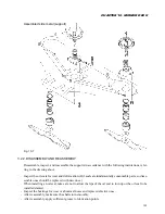
5) Installation of the gear and clutch
• Install the clutch assembly on the starter hous-
ing.
• Apply grease to the roller/retainer assembly and
idle gear and then install.
• Install the drive pinion on the armature shaft.
• Apply grease to each gear.
Fig. 9-30
6) Installation of the starter housing
• Install the starter housing on the magnetic switch.
• Install the two through bolts.
7) Connection of the lead of terminal C
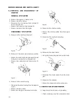
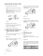
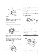
5.5. INSPECTION OF THE STARTER AFTER
REMOVAL FROM THE TRACTOR
Note:
Each step should be performed within three to
five seconds to prevent damage.
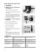
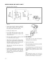
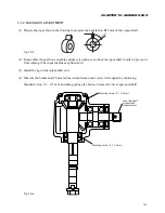
1) Pull-in test
• Make sure the pinion is pushed out when the
starter is connected as illustrated.
Fig. 9-31
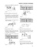
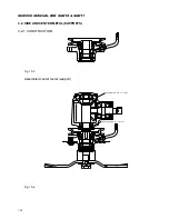
2) Coil holding test
• In the state of the pull-in test, the gear should
remain pushed out when the lead is disconnected
from terminal C.
Fig. 9-32
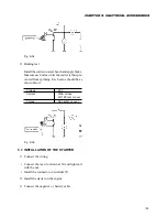
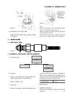
3) Plunger-return test
• In the state of the coil holding test, the pinion
should retract when the connection is removed
as illustrated.
Fig. 9-33
5.6. PERFORMANCE TEST
Note:
• Hold the starter securely in a vise.
• In unloaded test use thick wires because of high
current.
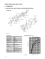
1) Unloaded test
Drive the starter independently with a specified
battery without any load and check for spinning
speed, voltage, and current. Values should be as
shown below:
Voltage
11.5 V
Current
90A or less
Speed
3000 rpm or more
Содержание SCM49
Страница 1: ...S E R V I C E M A N U A L I S E K I L A W N M O W E R S LAWN MOWERS MOWER DECKS SCM48 SCM54 ...
Страница 7: ...7 CHAPTER 1 INTRODUCTION 3 EXTERIOR VIEW AND DIMENSIONS 1935 mm 1965 mm 1100 mm 1265 mm ...
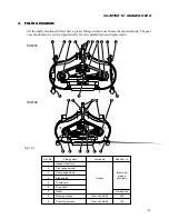
Страница 36: ...36 SERVICE MANUAL FOR SGR19 SGR17 Fig 3 55 III 3 CYLINDER BLOCK 1 EXPLODED VIEWS ...
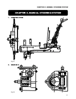
Страница 97: ...97 CHAPTER 8 MANUAL STEERING SYSTEM CHAPTER 8 MANUAL STEERING SYSTEM 1 CONSTRUCTION Fig 8 1 2 GEAR BOX Fig 8 2 ...