27
CHAPTER 3. ENGINE
1
2
3
4
5
6
7
8
9
10
11
12
13
14
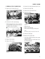
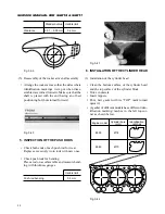
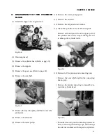
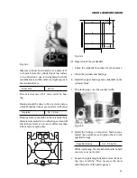
(5) Removal of the rocker shaft assembly (Fig. 3-20).
(6) Removal of the push rods.
(7) Removal of the water by-pass hose.
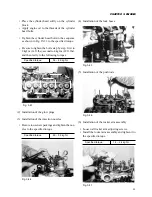
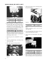
(8) Removal of nozzles.
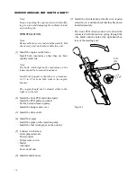
Fig. 3-22
• Remove the cap.
• Remove fuel-return pipes.
• Draw out the nozzle along with the gasket.
Note:
Be careful to keep the nozzle free from dust.
(9) Removal of glow plugs.
(10) Removal of the cylinder head.
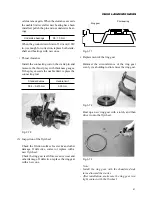
• Loosen the cylinder head bolts in the sequence
shown in the figure.
• After the removal of the cylinder head, remove
the dowels and tappets.
Fig. 3-23
1. REMOVAL OF THE CYLINDER HEAD
(1) Removal of the cylinder head cover.
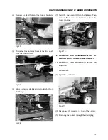
Fig. 3-19
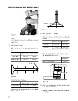
(2) Disconnection of the injection piping.
• When the piping has been removed, cap the de-
livery pipe holders, injection nozzles and injec-
tion pipes at once to avoid dust.
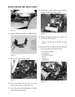
Fig. 3-20
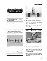
(3) Removal of the fan belt.
(4) Removal of the oil pipe.
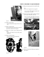
Fig. 3-21
Содержание SCM49
Страница 1: ...S E R V I C E M A N U A L I S E K I L A W N M O W E R S LAWN MOWERS MOWER DECKS SCM48 SCM54 ...
Страница 7: ...7 CHAPTER 1 INTRODUCTION 3 EXTERIOR VIEW AND DIMENSIONS 1935 mm 1965 mm 1100 mm 1265 mm ...
Страница 36: ...36 SERVICE MANUAL FOR SGR19 SGR17 Fig 3 55 III 3 CYLINDER BLOCK 1 EXPLODED VIEWS ...
Страница 97: ...97 CHAPTER 8 MANUAL STEERING SYSTEM CHAPTER 8 MANUAL STEERING SYSTEM 1 CONSTRUCTION Fig 8 1 2 GEAR BOX Fig 8 2 ...

