24
SERVICE MANUAL FOR SGR19 & SGR17
(7) Make sure that fuel ejects from the delivery
holder. Turn the crankshaft slowly in correct di-
rection (clockwise viewed from the fan) until fuel
ejection stops. The injection timing is just be-
fore fuel ejection stops.
• When fuel ejection stops, the injection timing
point is passed. Turn the crankshaft in reverse
and repeat operation 6).
• Even when the injection timing point is passed,
there is no sign of fuel ejection stopping. The
point is BTDC in exhaust stroke. Turn the crank-
shaft fully by 360
°
and start operation.
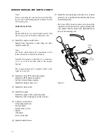
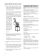
• As a criterion of
“just before fuel
stops,” use the
time to take to re-
fill the fuel in the
end of the delivery
holder after blow-
ing it off. When it
takes 1 to 2 sec-
onds to refill, it is
the fuel injection
timing point.
Fig. 3-13
(8) Check to see the timing mark on the flywheel or
the crankshaft pulley is aligned as shown in “3.2.
Adjustment of valve clearance.”
For reference:
The crank angle 1
°
is about 1 mm on the crank-
shaft pulley and about 2.5 mm on the flywheel.
(9) Turn the key switch to “OFF” and close the fuel
cock.
(10) After checking to see the fuel injection timing is
correct, remove the delivery holder and install
the delivery spring and stopper. Then re-tighten
the delivery holder to the specified torque.
(11) Install the injection pipe and tighten the nut to
the specified torque.
Tightening torque
1.5 – 2.5 kgf·m
Fuel
Delivery
valve
Note:
- Supply fuel only when fuel injection timing is
measured [only for operation 6)].
- It is impossible to measure the fuel injection tim-
ing by turning the crankshaft in reverse
(counterclockwise viewed from the fan).
- During this operation, be sure to keep dust out
of the fuel system.
• Adjustment of injection timing
When the injection timing is improper, it should
be corrected.
The injection timing can be adjusted by chang-
ing the distance between the camshaft and pump
mounting surface with shims.
a. Remove the injection pump cover.
b. Remove the control link and starting spring from
the control rack.
c. Remove the injection pump.
- Shimming
Available adjusting shims: 0.1, 0.2, 0.3, 0.4 and
0.5 mm thick
For reference:
Injection timing shift with 0.1 mm thick shim-
ming by crank angle:
Sh0.1 mm ........... 1
°
delay
Shimming -0.1 mm ............ 1
°
advance
d. Install the injection pump.
e. Confirm that the injection timing is proper by
the operation mentioned above. Until the proper
fuel injection timing is attained, repeat steps from
c. to e.
f. Install the control link and starting spring on the
control rack and then the injection pump cover.
Note:
During this operation, be careful to keep dust
out of the fuel system.
Содержание SCM49
Страница 1: ...S E R V I C E M A N U A L I S E K I L A W N M O W E R S LAWN MOWERS MOWER DECKS SCM48 SCM54 ...
Страница 7: ...7 CHAPTER 1 INTRODUCTION 3 EXTERIOR VIEW AND DIMENSIONS 1935 mm 1965 mm 1100 mm 1265 mm ...
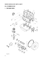
Страница 36: ...36 SERVICE MANUAL FOR SGR19 SGR17 Fig 3 55 III 3 CYLINDER BLOCK 1 EXPLODED VIEWS ...
Страница 97: ...97 CHAPTER 8 MANUAL STEERING SYSTEM CHAPTER 8 MANUAL STEERING SYSTEM 1 CONSTRUCTION Fig 8 1 2 GEAR BOX Fig 8 2 ...

