113
CHAPTER 9. ELECTRICAL ACCESSORIES
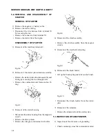
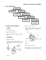
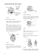
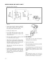
Fig. 9-45
Note:
Take care not to allow the rotor to fall to avoid
damaging the slip ring and fan.
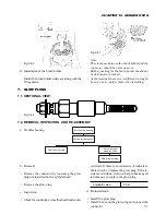
i. Removal of the retainer plate
Remove the four screws which tighten the re-
tainer plate. Then the plate is removed.
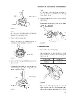
Fig. 9-46
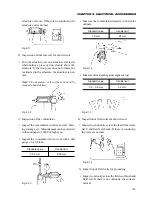
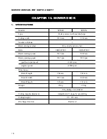
j. Removal of the bearing which is installed on the
drive end side
Place the drive end frame level on blocks as il-
lustrated and put a jig on the bearing. Then push
out the bearing on a press.
Fig. 9-47
Note:
The bearing is a high speed type, so be sure to
use a specified one by ISEKI when replacing.
Never give it shock.
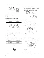
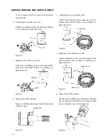
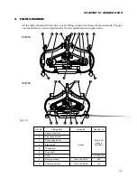
k. Removal of the baring which is installed on the
slip ring side
Remove the bearing using a puller as illustrated.
Fig. 9-48
6.4. INSPECTION
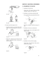
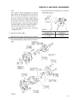
a. Inspection of the rotor slip rings
Measure the outer diameter of the rings. If the
measured value exceeds the usable limit, replace
with a new one.
Standard value
Usable limit
14.4 mm
14.0 mm
Fig. 9-49
• Make sure that the slip ring surface is smooth,
clean, and free from oil. If the surface is rough-
ened, polish with a fine sand paper (#500 – #600).
Содержание SCM49
Страница 1: ...S E R V I C E M A N U A L I S E K I L A W N M O W E R S LAWN MOWERS MOWER DECKS SCM48 SCM54 ...
Страница 7: ...7 CHAPTER 1 INTRODUCTION 3 EXTERIOR VIEW AND DIMENSIONS 1935 mm 1965 mm 1100 mm 1265 mm ...
Страница 36: ...36 SERVICE MANUAL FOR SGR19 SGR17 Fig 3 55 III 3 CYLINDER BLOCK 1 EXPLODED VIEWS ...
Страница 97: ...97 CHAPTER 8 MANUAL STEERING SYSTEM CHAPTER 8 MANUAL STEERING SYSTEM 1 CONSTRUCTION Fig 8 1 2 GEAR BOX Fig 8 2 ...


