

15
CHAPTER 2. DISASSEMBLY OF MAJOR COMPONENTS
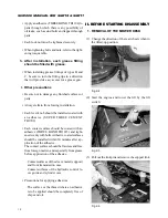
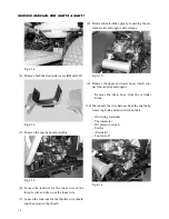
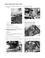
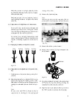
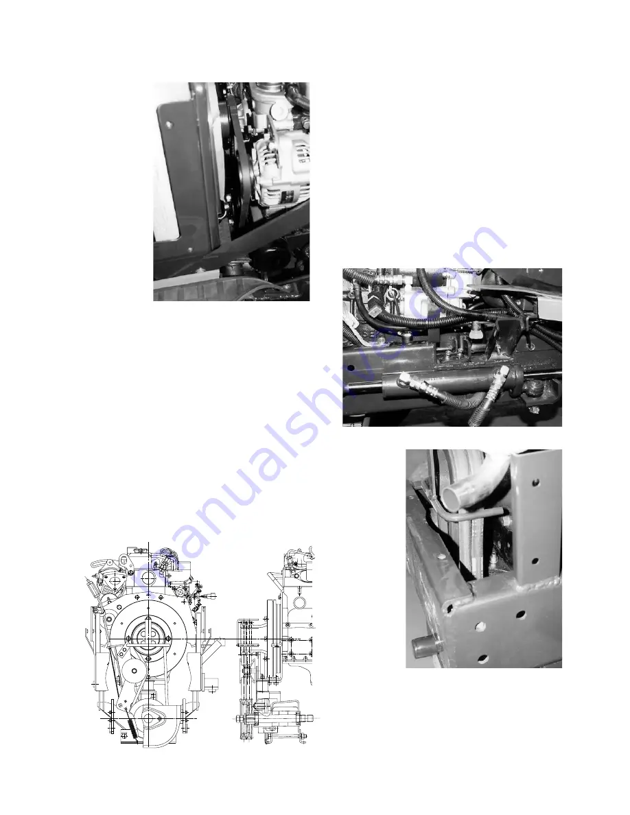
Fig. 2-17
(11) Remove the fuel pipes.
– Remove the fuel return pipes from the noz-
zles.
(12) Remove the drive shaft.
Loosen the bolts of the joint installed on the shaft
end which is connected to the engine.
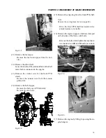
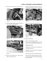
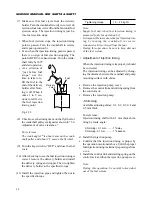
(13) Remove the control wire for the front PTO
clutch.
– Remove the tension wire from the tension
pulley arm.
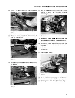
(14) Remove the belt stopper.
– Remove the belt cover (PTO shield).
– Remove the two belts.
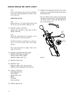
(15) Remove the snap-ring from the front PTO shaft.
Note:
Remove the spring from the tension pulley.
– Drive the front PTO shaft rearwards with a
plastic hammer or a mallet.
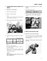
(16) Remove the engine stoppers which are clamped
on both sides of the frame with bolts.
– Remove the bolts which tighten the insulators:
two insulators on RH and LH and one in front.
Fig. 2-18
Fig. 2-19
Fig. 2-20
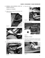
(17) Remove the engine by lifting it up using the en-
gine hangers.
Содержание SCM49
Страница 1: ...S E R V I C E M A N U A L I S E K I L A W N M O W E R S LAWN MOWERS MOWER DECKS SCM48 SCM54 ...
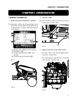
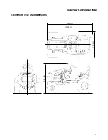
Страница 7: ...7 CHAPTER 1 INTRODUCTION 3 EXTERIOR VIEW AND DIMENSIONS 1935 mm 1965 mm 1100 mm 1265 mm ...
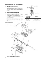
Страница 36: ...36 SERVICE MANUAL FOR SGR19 SGR17 Fig 3 55 III 3 CYLINDER BLOCK 1 EXPLODED VIEWS ...
Страница 97: ...97 CHAPTER 8 MANUAL STEERING SYSTEM CHAPTER 8 MANUAL STEERING SYSTEM 1 CONSTRUCTION Fig 8 1 2 GEAR BOX Fig 8 2 ...