58
SERVICE MANUAL FOR SGR19 & SGR17
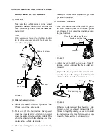
ADJUSTMENT OF THE BRAKES
(1) Brake arm
Make sure that the brake arm is in the vertical
position or slanted a little forward and does not
move forward any further while the brakes are
not applied.
Note:
If the arm moves forward any further, check it
for its spline engagement on the brake arm. Re-
assemble it if required.
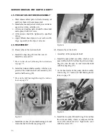
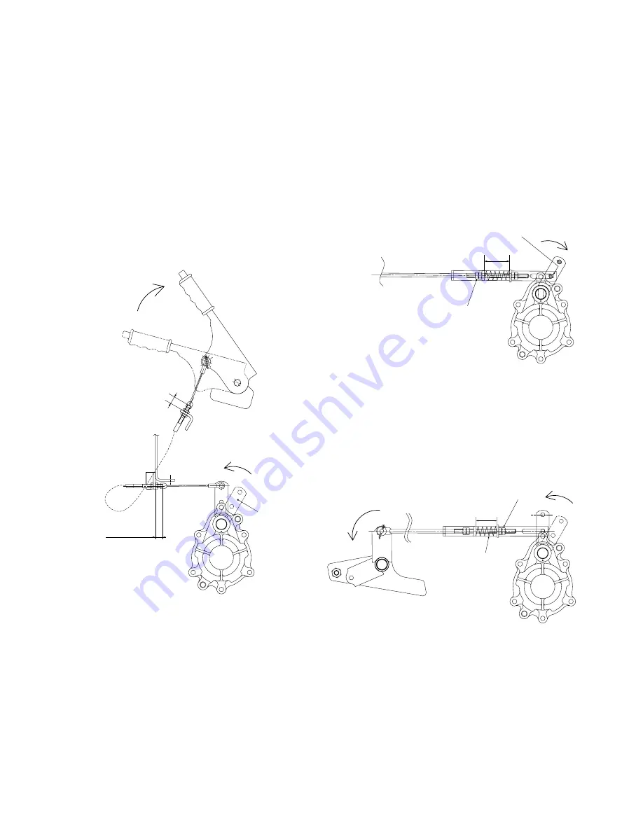
24– 25 mm
Parking brake lever
Brake arm
Reference value:
about 20 mm
Play of the pin at the end of the slot
should be less than 1 mm.
Front nut
47 mm
Rear nut
Brake return spring
41 – 42 mm
Fig. 4-20
(2) Parking brake adjustment
a. Set the wire sheath end so that it protrudes 24 to
25 mm beyond the cable holder.
b. Make sure that the four notches have passed
when the brake lever is pulled up to the end,
where the brake arm is pulled forward fully. This
should be adjusted with the adjusting nuts at the
cable end on the brake lever side.
c. When the parking brake lever is pushed down,
make sure the brake arm returns to the previous
position without fail.
(3) Foot brake adjustment
a. Make sure the clearance of the brake arm pin in
the slot is less than 1 mm when the brake pedals
are released. If not, correct the position by turn-
ing the front nut.
Fig. 4-21
b. Adjust the length of the spring to be 47 mm by
turning the rear nut when the brake pedals are
released.
c. Depress the brake pedals to the end and make
sure the length of the spring is 41 to 42 mm and
clearance between coils is maintained.
Fig. 4-22
If there is no clearance at all or the spring is de-
formed, correct the released spring so it is 47 to
50 mm in length by turning the rear nut in order
to provide proper clearance between spring coils
when the brake pedals are depressed fully.
Содержание SCM49
Страница 1: ...S E R V I C E M A N U A L I S E K I L A W N M O W E R S LAWN MOWERS MOWER DECKS SCM48 SCM54 ...
Страница 7: ...7 CHAPTER 1 INTRODUCTION 3 EXTERIOR VIEW AND DIMENSIONS 1935 mm 1965 mm 1100 mm 1265 mm ...
Страница 36: ...36 SERVICE MANUAL FOR SGR19 SGR17 Fig 3 55 III 3 CYLINDER BLOCK 1 EXPLODED VIEWS ...
Страница 97: ...97 CHAPTER 8 MANUAL STEERING SYSTEM CHAPTER 8 MANUAL STEERING SYSTEM 1 CONSTRUCTION Fig 8 1 2 GEAR BOX Fig 8 2 ...

