


46
SERVICE MANUAL FOR SGR19 & SGR17
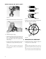
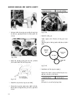
Fig. 3-89
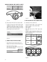
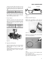
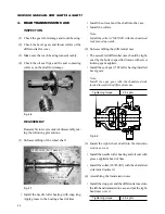
• Install the other snap ring securely in the groove.
Fig. 3-91
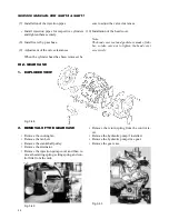
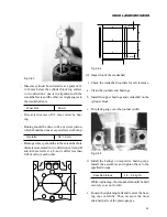
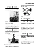
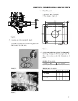
• Install the rings with their gaps 120
°
apart from
each other as shown in the figure.
Fig. 3-90
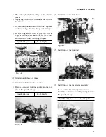
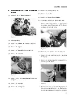
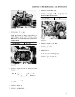
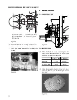
(2) Installation of piston rings
• Install the rings using a piston ring expander with
their “T” marks turned upwards. But the oil rings
have no markings, so they can be installed with
either side up.
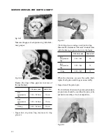
• The gaps of the ring and ring expander of the oil
ring should be set apart 180
°
from each other.
Note:
As No.1 and No.2 compression rings have dif-
ferent cross sections, take care not to install them
in wrong order.
No. 2
compression
ring
No. 1
compression
ring
Expander
joint
Oil ring
27
°
Front
Fig. 3-92
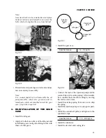
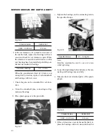
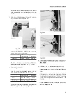
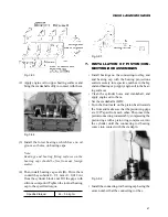
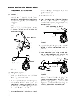
6.
INSTALLATION OF CRANKSHAFT
(1) Install the upper bearings, which have oil grooves
or oil holes, in the cylinder block.
Note:
Bearings and bearing fitting surfaces on the cyl-
inder block should be free from any foreign mat-
ter.
The projection of each bearing should be se-
curely seated in its notch in the cylinder block.
FRONT
1st
2nd
Oil
Chrome-plated
Chrome-plated
Coil expanders
Содержание SCM49
Страница 1: ...S E R V I C E M A N U A L I S E K I L A W N M O W E R S LAWN MOWERS MOWER DECKS SCM48 SCM54 ...
Страница 7: ...7 CHAPTER 1 INTRODUCTION 3 EXTERIOR VIEW AND DIMENSIONS 1935 mm 1965 mm 1100 mm 1265 mm ...
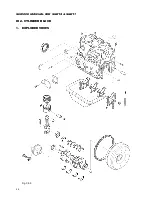
Страница 36: ...36 SERVICE MANUAL FOR SGR19 SGR17 Fig 3 55 III 3 CYLINDER BLOCK 1 EXPLODED VIEWS ...
Страница 97: ...97 CHAPTER 8 MANUAL STEERING SYSTEM CHAPTER 8 MANUAL STEERING SYSTEM 1 CONSTRUCTION Fig 8 1 2 GEAR BOX Fig 8 2 ...