


28
SERVICE MANUAL FOR SGR19 & SGR17
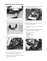
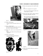
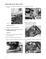
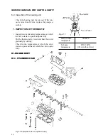
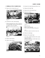
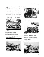
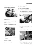
2. DISASSEMBLY
(1) Removal of the inlet manifold.
(2) Removal of the exhaust manifold.
(3) Removal of the thermostat housing.
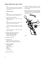
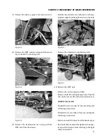
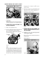
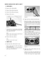
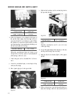
(4) Removal of the valves.
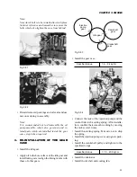
Fig. 3-24
• Compress the valve spring along with the spring
seat with a spring compressor, and remove the
cotter spring seat retainer.
Note:
Removed valve and related parts should be put
aside in order of valve numbers.
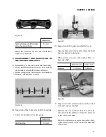
(5) Removal of the valve oil seals.
Note:
Discard removed valve oil seals.
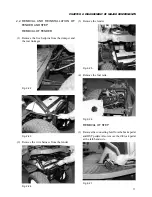
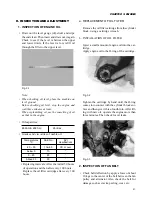
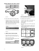
3. INSPECTION
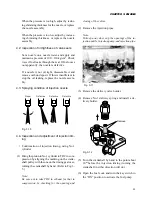
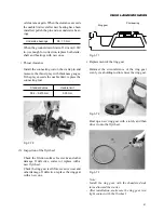
(1) Inspection of the cylinder head for cracks.
• Remove carbon deposit from the bottom surface
of the cylinder head.
• Inspect the bottom surface and inlet and exhaust
ports using “COLOR CHECK.”
Fig. 3-25
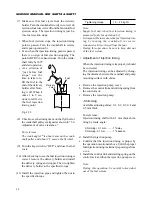
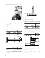
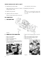
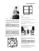
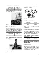
(2) Inspection of the cylinder head for distortion
• Measure the flatness of the bottom surface of
the cylinder head by putting a straight rule di-
agonally across the four corners on the bottom
face and check for clearance with thickness
gauges.
Standard value
Usable limit
Distortion
0.075 mm
0.15 mm
• When the distortion exceeds the usable limit,
correct on a surface grinder.
• As the ground-down limit is 0.4 mm (0.016 in.),
replace a cylinder head assembly which required
more than the ground-down limit to correct.
Fig. 3-26
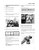
(3) Inspection of the clearance between the valve
guide and valve stem.
• Check the valve for play with a dial indicator. If
the play exceeds 0.15 mm for the inlet valve and
0.2 mm for the exhaust valve, replace both the
Содержание SCM49
Страница 1: ...S E R V I C E M A N U A L I S E K I L A W N M O W E R S LAWN MOWERS MOWER DECKS SCM48 SCM54 ...
Страница 7: ...7 CHAPTER 1 INTRODUCTION 3 EXTERIOR VIEW AND DIMENSIONS 1935 mm 1965 mm 1100 mm 1265 mm ...
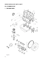
Страница 36: ...36 SERVICE MANUAL FOR SGR19 SGR17 Fig 3 55 III 3 CYLINDER BLOCK 1 EXPLODED VIEWS ...
Страница 97: ...97 CHAPTER 8 MANUAL STEERING SYSTEM CHAPTER 8 MANUAL STEERING SYSTEM 1 CONSTRUCTION Fig 8 1 2 GEAR BOX Fig 8 2 ...