

105
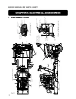
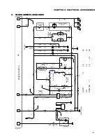
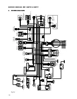
CHAPTER 9. ELECTRICAL ACCESSORIES
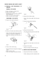
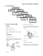
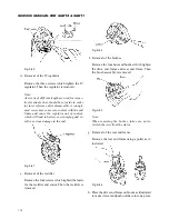
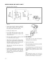
armature coil core. If there is no continuity, the
armature coil is normal.
Fig. 9-11
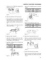
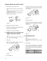
2) Inspection of armature coil for short circuit
• Turn the armature coil on a armature coil tester
while holing a piece of iron closely above the
armature. If the iron piece does not vibrate nor
is attracted to the armature, the armature is nor-
mal.
Note: The armature coil surfaces should be
cleaned ahead of time.
Fig. 9-12
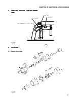
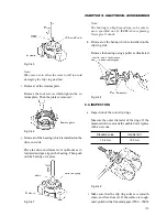
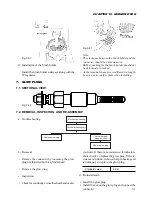
3) Inspection of the commutator
• Inspect the commutator surfaces for dirt, burn-
ing, damage, etc. Minor damage can be corrected
with sandpaper of #400 or higher no.
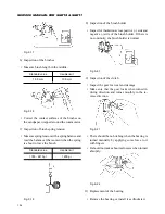
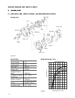
• Inspect the commutator for run-out with a dial
gauge on a V-block.
Standard value
Usable limit
0.02 mm
0.05 mm
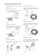
• Measure the commutator diameter with vernier
calipers.
Standard value
Usable limit
30 mm
29 mm
Fig. 9-14
• Measure mica depth against segment top.
Standard value
Usable limit
0.5 - 0.8 mm
0.2 mm
Fig. 9-15
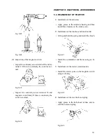
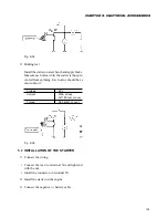
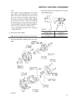
4) Inspection of field coils for short circuit
• Inspect for continuity across the lead from termi-
nal C and field coil brush. If there is continuity,
the coils are normal.
Fig. 9-16
5) Inspection of field coils for grounding
• Inspect continuity across the field coil brush and
field coil. If there is no continuity, the coils are
normal.
Fig. 9-13
Содержание SCM49
Страница 1: ...S E R V I C E M A N U A L I S E K I L A W N M O W E R S LAWN MOWERS MOWER DECKS SCM48 SCM54 ...
Страница 7: ...7 CHAPTER 1 INTRODUCTION 3 EXTERIOR VIEW AND DIMENSIONS 1935 mm 1965 mm 1100 mm 1265 mm ...
Страница 36: ...36 SERVICE MANUAL FOR SGR19 SGR17 Fig 3 55 III 3 CYLINDER BLOCK 1 EXPLODED VIEWS ...
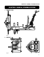
Страница 97: ...97 CHAPTER 8 MANUAL STEERING SYSTEM CHAPTER 8 MANUAL STEERING SYSTEM 1 CONSTRUCTION Fig 8 1 2 GEAR BOX Fig 8 2 ...