
117
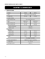
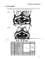
CHAPTER 10. MOWER DECK
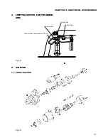
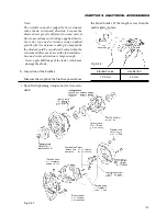
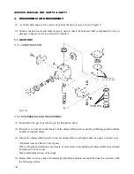
7.
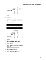
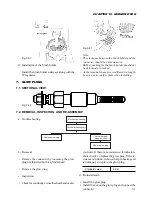
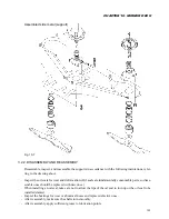
GLOW PLUGS
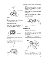
7.1. SECTIONAL VIEW
Fig. 9-62
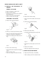
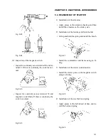
7.2. REMOVAL, INSPECTION, AND RE-ASSEMBLY
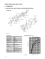
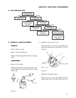
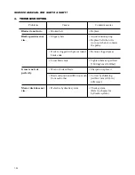
a. Troubleshooting
b. Removal
• Remove the connector by loosening the glow
plug nut installed on the cylinder head.
• Remove the glow plug.
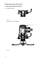
c. Inspection
• Check for continuity across the sheath and center
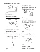
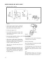
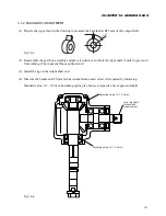
Fig. 9-60
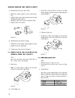
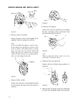
2) Installation of the brush holder
Install the brush holder sideways along with the
IC regulator.
Fig. 9-61
Note:
- The clearance between the brush holder and the
connector should be 1 mm or more.
- Rubber packing for the brush holder should not
be deformed or pinched.
- As the terminals have screws different in length,
be sure not to confuse them when installing.
electrode. If there is no resistance, it indicates a
short circuit, so replace the glow plug. If the re-
sistance is infinite, it shows that pre-heating coil
is burnt out, so replace the glow plug.
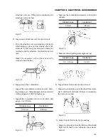
Standard value
2.0
Ω
d. Re-installation
• Install the glow plug.
• Install the nut on the glow plug and connect the
connector.
Improper preheating
Check pre-heating coil.
Replace glow plug.
Check other inner
wiring for short.
Replace glow plug.
Содержание SCM49
Страница 1: ...S E R V I C E M A N U A L I S E K I L A W N M O W E R S LAWN MOWERS MOWER DECKS SCM48 SCM54 ...
Страница 7: ...7 CHAPTER 1 INTRODUCTION 3 EXTERIOR VIEW AND DIMENSIONS 1935 mm 1965 mm 1100 mm 1265 mm ...
Страница 36: ...36 SERVICE MANUAL FOR SGR19 SGR17 Fig 3 55 III 3 CYLINDER BLOCK 1 EXPLODED VIEWS ...
Страница 97: ...97 CHAPTER 8 MANUAL STEERING SYSTEM CHAPTER 8 MANUAL STEERING SYSTEM 1 CONSTRUCTION Fig 8 1 2 GEAR BOX Fig 8 2 ...