


72
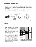
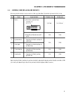
SERVICE MANUAL FOR SGR19 & SGR17
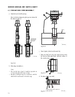
Fig. 5-30
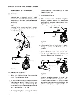
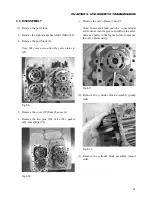
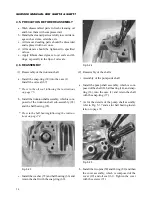
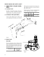
d. Installl the thrust bearing onto the slant board
assembly, which includes the swash plate (4) and
bush (17). Install the slant board so that the
groove in the slant board is aligned with the slid-
ing piece.
Install the thrust bearing so that the side having
no marking is turned towards the pistons.
* As for the details of the slant board and installa-
tion of the bush, refer to page 74.
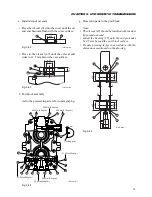
Fig. 5-31
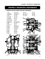
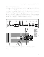
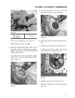
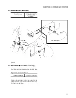
(4) Installation of the cylinder blocks
a. Install the cylinder block assembly, which is
composed of the cylinder block (3), pistons (5),
springs (20) and spring holders (41) respectively
onto the motor and pump shafts.
When installing the cylinder block, apply work-
ing fluid to the pistons ahead of time.
* As for the details of the cylinder block, refer to
Fig. 5-1.
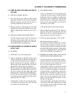
Fig. 5-32
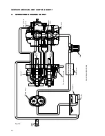
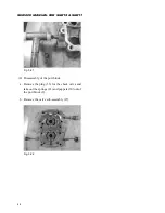
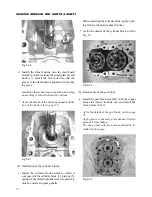
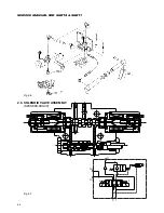
(5) Reassembly of the port block
a. Install the port block assembly with the copper
alloy side turned towards you and install the
valve plates (6 & 7).
– As for the details of the port block, refer to page
75.
Apply grease to the valve plate ahead of time to
prevent it from falling.
The valve plate with two notches should be in-
stalled on the pump.
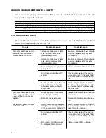
Fig. 5-33
Содержание SCM49
Страница 1: ...S E R V I C E M A N U A L I S E K I L A W N M O W E R S LAWN MOWERS MOWER DECKS SCM48 SCM54 ...
Страница 7: ...7 CHAPTER 1 INTRODUCTION 3 EXTERIOR VIEW AND DIMENSIONS 1935 mm 1965 mm 1100 mm 1265 mm ...
Страница 36: ...36 SERVICE MANUAL FOR SGR19 SGR17 Fig 3 55 III 3 CYLINDER BLOCK 1 EXPLODED VIEWS ...
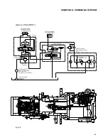
Страница 97: ...97 CHAPTER 8 MANUAL STEERING SYSTEM CHAPTER 8 MANUAL STEERING SYSTEM 1 CONSTRUCTION Fig 8 1 2 GEAR BOX Fig 8 2 ...