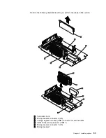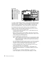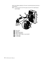
1
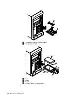
DIMM
2
Retaining clips
3
DIMM connector 1 (J4)
4
DIMM connector 2 (J3)
5
DIMM connector 3 (J2)
6
DIMM connector 4 (J1)
Before you begin:
Read “Electrical safety” on page 42 and “Handling static-sensitive devices”
on page 44.
Read the documentation that comes with your option.
To install a DIMM:
1. Turn off the server and peripheral devices and disconnect all external cables
and power cords (see “Preparing to install options” on page 46); then remove
the cover. See “Removing the left-side cover (tower model)” on page 48 or
“Removing the cover (rack model)” on page 49.
2. Locate the DIMM connectors on the processor board. Determine the DIMM
connector into which you will install the DIMM. (See the notes at the beginning
of this procedure.)
3. Touch the static-protective package containing the DIMM to any unpainted
metal surface on the server. Then, remove the DIMM from the package.
Note: To avoid breaking the retaining clips or damaging the DIMM connectors,
handle the clips gently.
4. Install the DIMM:
a. Turn the DIMM
1
so that the pins align correctly with the connector
5
.
b. Insert the DIMM into the connector by pressing on one edge of the DIMM
and then on the other edge of the DIMM. Be sure to press straight into the
connector. Be sure that the retaining clips
2
snap into the closed
positions.
c. Make sure the retaining clips are in the closed position. If a gap exists
between the DIMM and the retaining clips, the DIMM has not been properly
installed. In this case, open the retaining clips and remove the DIMM; then,
reinsert the DIMM.
d. Repeat these steps for each DIMM that you install.
Attention:
Installing or removing DIMMs changes the configuration information in the
server. When you restart the server, the system displays a message indicating
that the memory configuration has changed.
If you installed additional memory, start the Configuration/Setup Utility
program and select Save Settings.
If you just replaced a failed DIMM, you must start the Configuration/Setup
Utility program, select Advanced Setup, select Memory Settings, highlight
the connector or bank of connectors that you want to enable, then select
Enable.
66
IBM xSeries User's Reference
Содержание eServer 240 xSeries
Страница 1: ...User s Reference xSeries 240...
Страница 26: ...16 IBM xSeries User s Reference...
Страница 50: ...40 IBM xSeries User s Reference...
Страница 116: ...106 IBM xSeries User s Reference...
Страница 170: ...160 IBM xSeries User s Reference...
Страница 180: ...170 IBM xSeries User s Reference...
Страница 219: ...IBM Part Number 21P9014 Printed in the United States of America 21P9 14...

