17
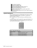
PCI slot Power Good LEDs
18
Internal PCI slot Attention LEDs
19
External PCI slot Attention LEDs
2
Advanced System Management adapter connector (J21)
21
External LVD SCSI/Parallel port connectors (J19)
22
Serial/video port connectors (J11)
23
USB 1 and USB 2 port connectors (J9) (USB 2 is below USB 1.)
24
Ethernet port connector (J7)
25
Mouse and keyboard connectors (J5) (The mouse connector is above the
keyboard connector.)
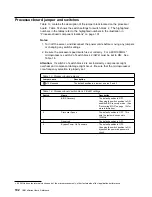
System-board jumpers
Table 12 describes the jumpers on the system board. The numbers in the table
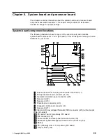
correspond to the highlighted numbers on the illustration in “System-board
component locations” on page 99.
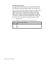
Note: Turn off the server, and disconnect the power cords before moving any
jumpers.
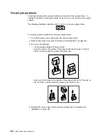
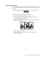
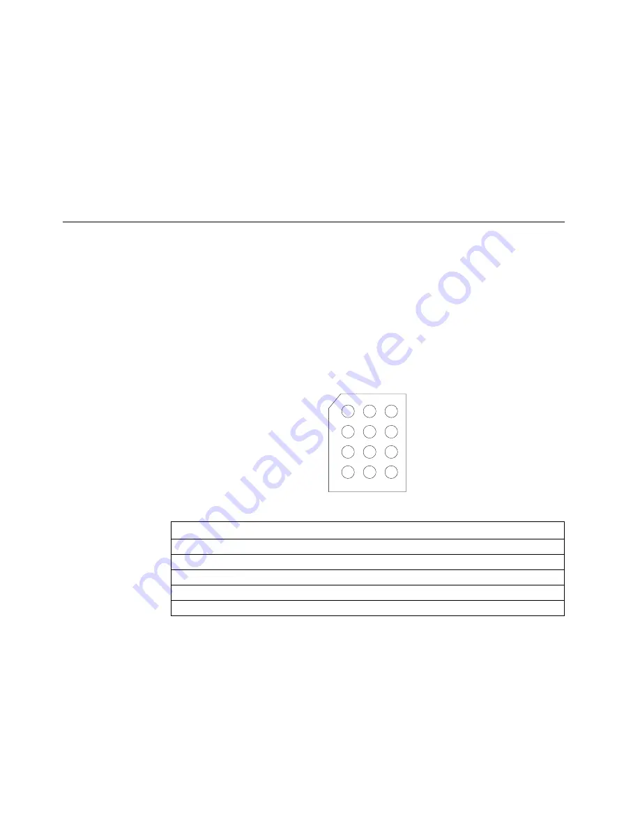
The following illustration shows pin positions for the system board jumper J20. Pin
1 is the pin at the upper-left corner of J20 in the illustration of the system board in
“System-board component locations” on page 99.
1 2 3
10 11 12
4
7
6
9
Table 12. System board jumper (J20)
Jumper pin positions
Description
Pins 1–3
The default is no jumper on pins 1, 2, and 3.
Pins 4–6
The default is a jumper on pins 4 and 5.
Pins 7–9
The default is a jumper on pins 8 and 9.
Pins 10–12
The default is a jumper on pins 10 and 11.
100
IBM xSeries User's Reference
Содержание eServer 240 xSeries
Страница 1: ...User s Reference xSeries 240...
Страница 26: ...16 IBM xSeries User s Reference...
Страница 50: ...40 IBM xSeries User s Reference...
Страница 116: ...106 IBM xSeries User s Reference...
Страница 170: ...160 IBM xSeries User s Reference...
Страница 180: ...170 IBM xSeries User s Reference...
Страница 219: ...IBM Part Number 21P9014 Printed in the United States of America 21P9 14...

