

Resolving configuration conflicts
The Configuration/Setup Utility program configures only the server hardware. It
does not consider the requirements of the operating system or the application
programs. For these reasons, memory-address configuration conflicts might occur.
Changing the software configuration setup
The best way to resolve memory-address conflicts is to change the software
configuration by changing the addresses that the EMS device driver defined. The
SVGA video memory occupies 32 KB (1 KB
=
approximately 1000 bytes) of space
in the hex C0000 to C7FFF EMS memory area. EMS device drivers must use
addresses different from those assigned to video read-only memory (ROM). You
can use the Configuration/Setup Utility program to view or change the current
setting for video ROM. For information about using the Configuration/Setup Utility
program, see “Using the Configuration/Setup Utility main menu” on page 21.
Changing the hardware configuration setup
An alternative way to resolve memory-address conflicts is to change the address of
the conflicting hardware option.
Identifying problems using status LEDs
Your server has LEDs to help you identify problems with some server components.
These LEDs are part of the light path diagnostics built into the server. By following
the path of lights, you can quickly identify the type of system error that occurred.
See “Light path diagnostics” on page 153 for more information.
Status LEDs are located on the following components:
Operator information panel
For more information, see “Operator information panel” on page 10.
Hard disk drive trays
For more information, see “Controls and indicators” on page 7.
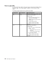
Power supply
For more information, see “Power supply LEDs” on page 152.
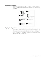
Diagnostic LED panel
For more information, see “Diagnostic LED panel” on page 153.
System board
See “System-board component locations” on page 99 for locations of the LEDs
on the system board.
Processor board
See “Processor-board component locations” on page 101 for locations of the
LEDs on the processor board.
Chapter 6. Solving problems
151
Содержание eServer 240 xSeries
Страница 1: ...User s Reference xSeries 240...
Страница 26: ...16 IBM xSeries User s Reference...
Страница 50: ...40 IBM xSeries User s Reference...
Страница 116: ...106 IBM xSeries User s Reference...
Страница 170: ...160 IBM xSeries User s Reference...
Страница 180: ...170 IBM xSeries User s Reference...
Страница 219: ...IBM Part Number 21P9014 Printed in the United States of America 21P9 14...