Shenzhen Hpmont Technology Co., Ltd.
Chapter 6 Function Introduction
HD3N Series User Manual V1.1
- 77 -
Ref. code
Function Description
Setting Range [Default]
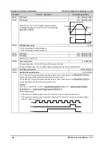
37: Reset wobble state.
•
When select wobble function (F07.00 = 1), no matter automatic or manual mode (F07.01), DI6 = 37 will
reset wobble state.
38: Stop DC brake input.
•
Apply DC brake to motor which is in stop status via control terminal. Refer to F02.04 for braking current.
•
The terminal is valid in dec to stop process and DC brakes motor immediately. When invalid, DC brake
stops.
39,40: External stop NO/NC contact input.
•
In running, when HD3N receives external stop signal, it stops output.
•
When external stop signal is cancelled and HD3N can run, it tracks and start running.
41,42: Coast to stop NO/NC input.
•
After HD3N receives command, it stops output at once, the load will coast to stop according to
mechanical inertia.
43: Emergency stop.
•
After HD3N receives command, it decelerates to stop. The dec time is set by F03.17.
44,45: NO/NC input for external fault.
•
HD3N can detect fault of external device and acts according to F15.17.
•
HD3N shows external device’s fault after receiving fault signal.
•
Two input modes for fault signal: NO or NC.
46: External reset (RST) input. Reset fault when HD3N has fault.
•
It has the same function as
button (
) on keypad.
48: Timing input. Used on timming input terminal.
•
Refer to F15.25 and F15.26.
49: Input for clearing actual length.
•
Input terminal for clearing actual length of length control.
•
Refer to F19.26 - F19.34.
50: Signal input to clear counter. To clear value of counter in HD3N.
•
Used together with No. 51 function (triggering signal input of counter).
51: Triggering signal input of counter.
•
Counting pulse input of counter can save current counting value at power failure.
•
Max. pulse. frequency: 200Hz.
•
Refer to F15.37 and F15.38.
52: Length counting input (DI6 only). Length input terminal under length control.
•
Refer to F19.26 - F19.34.
53: Pulse frequency input (DI6 only). It receives pulse signal as frequency setting.
•
Refer to F05 for relationship of input signal pulse frequency and setting frequency.
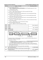
54: Switch main/aux frequency source.
56: Switch speed control and torque control.
•
Valid: F00.00 = 0, switch to torque control; F00.00 = 1, switch to speed control.
•
Invalid: Set by F00.00 (control mode selection).
57: Polarity switching of torque control.
•
Valid: Reverse direction of that by F21.
•
Invalid: Direction set by F21.
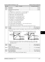
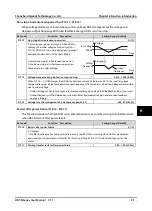
59: Switch PID parameter.
6

