Chapter 6 Function Introduction
Shenzhen Hpmont Technology Co., Ltd.
- 82 -
HD3N Series User Manual V1.1
Ref. code
Function Description
Setting Range [Default]
F15.31
FDT1 level
0.00 – F00.08 [5.00Hz]
F15.32
FDT1 delay
0.00 – F00.08 [0.00Hz]
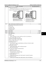
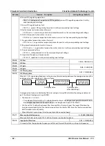
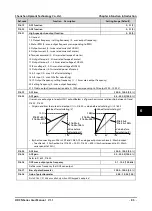
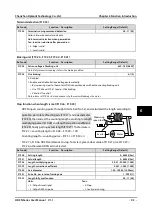
When F15.30 > F15.31, HD3N outputs command signal
until output frequency is lower than FDT1 level and delay
(FL) (F15.31 - F15.32).
F15.33
FDT2detection mode
0,1 [0]
0: Detect according to setting frequency.
1: Detect according to output frequency.
F15.34
FDT2 level
0.00 – F00.08 [5.00Hz]
F15.35
FDT2delay
0.00 – F00.08 [0.00Hz]
Refer to F15.31 and F15.32.
F15.36
Set running times
0 - 65535 [0h]
If accumulative time = F15.36, HD3N has a 500ms mark internally.
If output terminal/relay = No. 21, HD3N outputs according to correct internal control status.
F15.37
Set fully counting value
F15.38 - 9999 [0]
F15.38
Specific fully counting value
0 - F15.37 [0]
F15.37 defines DO terminal or relay outputing signal at certain input pulse when DI terminal ( = No. 51) at
certain input pulse. Meanwhile external counter will clear ot zero.
F15.38 defines DO terminal or relay outputing signal at certain input pulse when DI terminal ( = No. 51) at
certain input pulse until specific counting value is met.
Example:
Set F15.37 = 7 and F15.38 = 3, DO1 = counter fully met (F15.18 = 23), DO2 = specific counter fully met
(F15.19 = 24), DI1 = signal input to trigger counter (F15.00 = 51).
Refer to below figure:
•
DO2 outputs an indicating signal when DI1 inputs the 3
rd
pulse, until counting value = 7.
•
DO1 outputs an indicating signal when DO1 outputs the 7
th
pulse; DO1 resumes to low level voltage
when DI1 inputs the 9
th
pulse.
Output frequency
F15.32
F15.31
FL
Time
Time
DO
1
2
8
3
4
5
6
7
DI1
DO1
DO2

