Shenzhen Hpmont Technology Co., Ltd.
Chapter 6 Function Introduction
HD3N Series User Manual V1.1
- 81 -
Ref. code
Function Description
Setting Range [Default]
38: High speed pulse output (DO2 only).
•
Refer to F16.21.
F15.24
Terminal output logic setting
0 - 0x7 [0]
Terminal input logic setting. Defines that each bit (binary) represents different physical sources.
•
0: Positive logic. Connected to corresponding common port,
this logic is enabled. Otherwise disabled.
•
1: Negative logic. Connected to corresponding common port,
this logic is disabled. Otherwise enabled.
Bit3
Bit2
Bit1
Bit0
-
RLY1
DO2
DO1
123
F15.25
Delay time at ON side for timing
0.00 - 300.00 [0.00s]
F15.26
Delay time at OFF side for timing
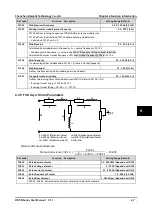
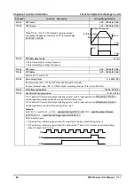
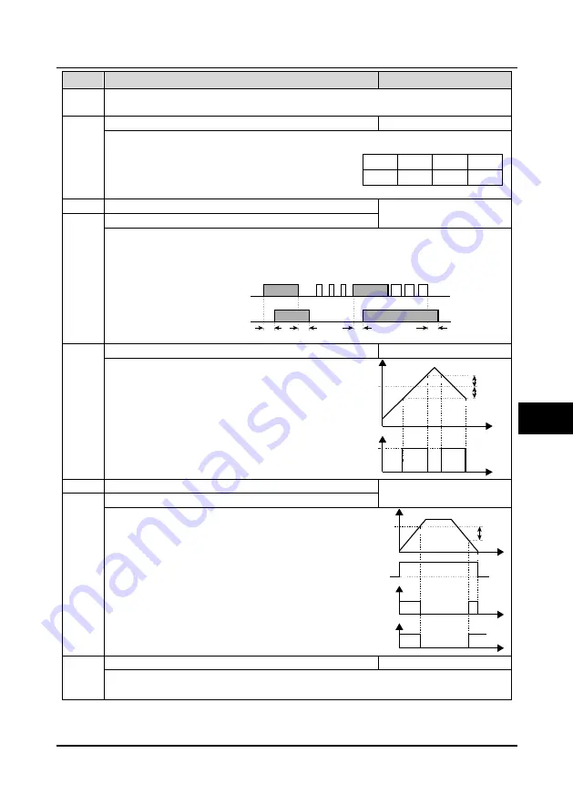
F15.25, F15.26 set delay time (dead zone) at ON/OFF side for timming function, relating to input.
•
Timing function output is ON when time of timing function input > F15.25.
•
Timing function output is OFF when time of timing function input < F15.25.
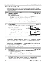
Below is figure of timing function action:
F15.27
Speed within FAR range
0.00 - 100.00 [2.50Hz]
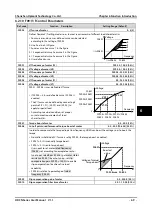
The pulse signal will output if elevator speed is within
the FAR range. As shown in the right figure.
F15.28
Zero speed threshold
0.00 - upper limit frequency
[0.00Hz]
F15.29
Zero speed tolerance
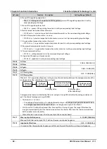
F15.28 and F15.29 defines the zero speed output
control function.
F15.30
FDT1 detection mode
0,1 [0]
0: Detect according to setting frequency.
1: Detect according to output frequency.
ON
ON
ON
ON
Timing function input
Timing function output
F15.25
F15.25
F15.26
F15.26
Output
Output
Time
Time
Preset frequency
DO
F15.27
F15.27
Running frequency
Zero-frequency
running output
F15.29
F15.28
Running status
Zero-frequency output
Time
Time
Time
6

